


Fiber-Optic SensorsD4RF/D4IF Series
Easy-to-Read, Easy-to-Use,
Fiber-Optic Sensors
- Easy-to-read OLED display
- Fiber insertion indicators to check insertion depth of Fiber-Optic Cables
- Large LED indicators for excellent visibility
NEW MODELS
Short-range/High accuracy type
Infrared light source type


- Infrared light source type (D4IF-T/D4IF-TC4)
Adopts the 1,450 nm wavelength that is easily absorbed by water (component)
Wide variety of infrared light source–related applications
■ Applications
-
Detection of Chemicals in Transparent Bottles
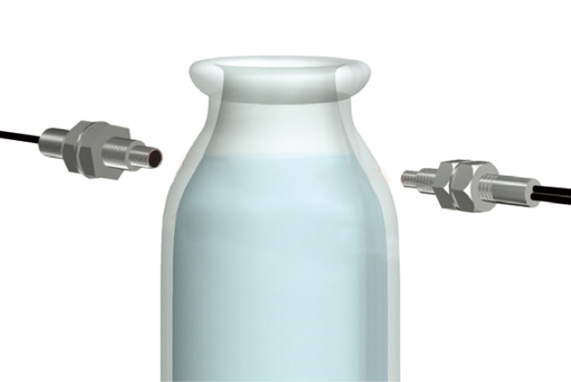
Infrared LED light at 1,450 nm, which is easily absorbed by water (component), allows detection of chemicals because the light is received when chemicals are not present and not received when chemicals block the optical axis.
-
Detection of Adhesives
Infrared light with a wavelength of 1,450 nm is easily absorbed by the water (component) in adhesives, so if adhesives is present, the light will be absorbed and the received light amount will decrease.
If no adhesives is present, the light will be reflected by the substrate, increasing the received light amount.
-
Silicon Solar Panel Overlap Detection
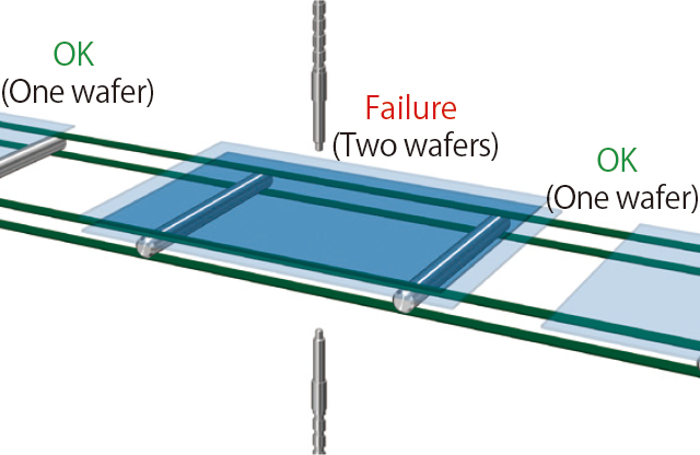
The moderate penetration of 1,450 nm wavelength infrared light with silicon solar panels makes it possible to detect overlaps based on the difference in received light amount of one wafer compared with twowafers.
-
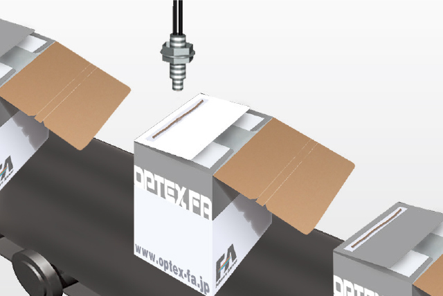
Pick-and-press Laminated Film Overlap Detection
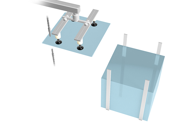
Because 1,450 nm infrared light is easily absorbed by films, the difference in the received light amount can be used to distinguish between one or two sheets even if the film is transparent.
- Short-range/High accuracy type
(D4RF-T-Y/D4RF-TD-Y/D4RF-TA-Y/D4RF-TDM-Y/D4RF-TDS-Y)
■ Detects small objects in a clean environment
■ Detects minute changes in light intensity
-
● Detection of small objects with only minute changes
in light intensity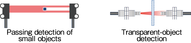
-
● Short-range detection of small objects

■ Applications
-
Passing Detection of Electronics Components
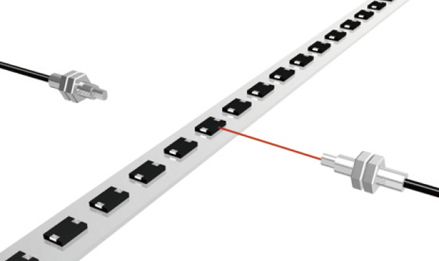
Sufficient light intensity ensures stable detection of passing objects.
-
Counting the Number of Dropped Screws/Small Objects
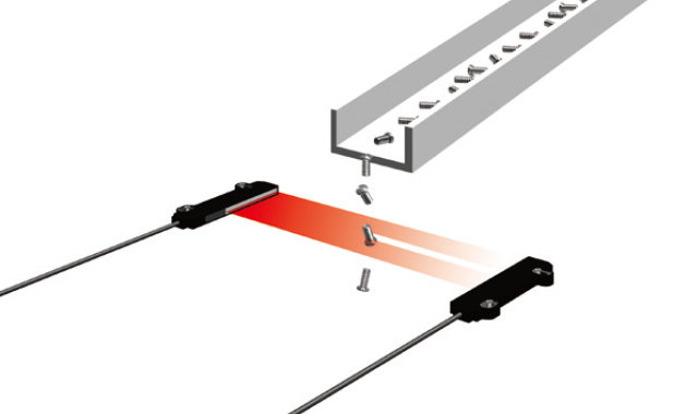
Sufficient light intensity ensures stable detection of passing objects.
- Analog output model (D4RF-TA/D4RF-TA-Y)
Selectable according to your analog devices
● Current output: 4 to 20 mA ● Voltage output: 0 to 10 V or 1 to 5 V
-
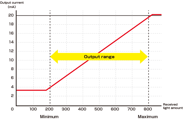
Manual adjustment of the analog output range
The analog output range set with the teach function can be changed manually.
【Setting examples】
When the received light amount is within the analog output range (200 to 800), a current of 4 to 20 mA is output.
Display the setting analog output values
(4 mA → 200、20 mA → 800) -
-
■ Application
-
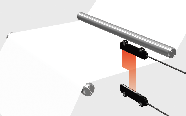
Detection of Film Meandering
Fiber-Optic Sensors with analog output can feedback the position of the edge by analog output.
Screen Fiber-Optic Cables NF-TS40 can be utilized for alignment control.
It has 40 mm width screen beam and in that area the sensor can detect edge of the film.
- Interconnection type for communication unit (D4RF-TM-0/D4RF-TS-0/D4RF-MC4/D4RF-S)
Select when using interconnection type for IO-Link or when using the interference prevention function.
Connect to PLC or IPC via communication unit
The lineup includes communication units with various interconnection types to meet diverse customer needs - for example, eliminating the display or operation keys by allowing settings and monitoring by PLC or IPC, or reducing cables.
・ Max. 16 units of Fiber-Optic Sensors can be connected.
・ Communication of output and identification.
・ Reduced wiring : Simply connect to gateway. Cable-less models are also available.
(When interconnecting four or more Fiber-Optic Sensors, supply power not only to the UC2-IOL but also to the
Fiber-Optic Sensors main unit on the left end.)
・ Low cost and low current consumption : Models without OLED displays are also available.

-

When connecting more than four Fiber-Optic Sensors to IO-Link Gateway UC2-IOL, additional 24 VDC power must be supplied to the terminal Fiber-Optic Sensor.
The 0 V of the supply power should be connected to the 0 V of the power supplied to IO-Link Master to match the potential.
If there are three or less Fiber-Optic Sensors, additional power is not required.
Connectable communication unit
-

By connecting D4RF to UC2-IOL, connected models that cannot communicate via IO-Link can be connected to IO-Link Master.
*Use UC2 with firmware version 2.1.0R or later (from lot 2307 or later). -

By connecting D4RF to UC1-EC, it can communicate with PLC via EtherCAT.
*Use UC1 with firmware version 1.1.0 or later.
-

By connecting D4RF to UC1-EP, it can communicate with PLC via EtherNet/IP.
*Use UC1 with firmware version 1.2.0 or later.