


Fiber-Optic SensorsD4RF/D4IF Series
Easy-to-Read, Easy-to-Use,
Fiber-Optic Sensors
- Easy-to-read OLED display
- Fiber insertion indicators to check insertion depth of Fiber-Optic Cables
- Large LED indicators for excellent visibility
NEW MODELS
Short-range/High accuracy type
Infrared light source type


I/O Circuit Diagrams
Stand-alone models (IO-Link device)
-
【1-output and 1-switchable-output/input type】*
(D4RF-T/D4RF-TC4/D4RF-T-Y/D4IF-T/D4IF-TC4)IO-Link mode

* When using NPN settings for an IO-Link connection, use OPTEX FA’s IO-Link Master UR Series or IO-Link Master with sink support.
-
【2-output and 1-input type】*
(D4RF-TD/D4RF-TD-Y)IO-Link mode

* When using NPN settings for an IO-Link connection, use OPTEX FA’s IO-Link Master UR Series or IO-Link Master with sink support.
【1-output and 1-switchable-output/input models】
(D4RF-T/D4RF-TC4/D4RF-T-Y/D4IF-T/D4IF-TC4)
-
SIO mode (standard I/O mode)
NPN setting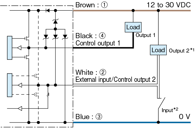
*1. When used as control output 2
*2. When used as external input -
SIO mode (standard I/O mode)
PNP setting or Push-pull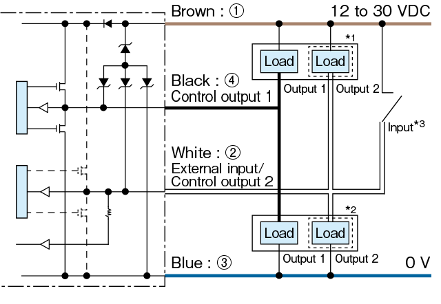
*1. When I/O polarity is set to Push-pull or NPN and the sensor is connected with plus common circuits.
*2. When I/O polarity is set to Push-pull or PNP and the sensor is connected with minus common circuits.
*3. When used as external input.
Connector type

【2-output and 1-input type】
(D4RF-TD/D4RF-TD-Y)
-
SIO mode (standard I/O mode)
NPN setting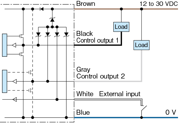
-
SIO mode (standard I/O mode)
PNP setting or Push-pull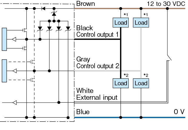
*1. When I/O polarity is set to Push-pull or NPN and the sensor is connected with plus common circuits.
*2. When I/O polarity is set to Push-pull or PNP and the sensor is connected with minus common circuits.
Analog output type
(D4RF-TA/D4RF-TA-Y)
-
NPN setting

-
PNP or Push-pull setting

*1. When I/O polarity is set to Push-pull and the sensor is connected with plus common circuits.
*2. When I/O polarity is set to Push-pull or PNP and the sensor is connected with minus common circuits.
Interconnection models
【1-output and 1-switchable-output/input type without display and keys】
(D4RF-TM/D4RF-TS/D4RF-TMC4/D4RF-TSC4/D4RF-MC4)
-
NPN setting

*1. When used as control output 2.
*2. When used as external input.
*3. Power supply wires (Brown ①, Blue ③) are not equipped on the inter-connection expansion units.
*4. Input and output wires (White ②, Black ④) are not equipped on models “Without output/input wires”. -
PNP or Push-pull setting

*1. When I/O polarity is set to Push-pull or NPN and the sensor is connected with plus common circuits.
*2. When I/O polarity is set to Push-pull or PNP and the sensor is connected with minus common circuits.
*3. When used as external input
*4. Power supply wires (Brown ①, Blue ③) are not equipped on the inter-connection expansion units.
*5. Input and output wires (White ②, Black ④) are not equipped on models “Without output/input wires”.
【2-output and 1-input type】
(D4RF-TDM/D4RF-TDM-Y/D4RF-TDS/D4RF-TDS-Y)
-
NPN setting

*1. Power supply wires (Brown, Blue) are not equipped on the inter-connection expansion units.
-
PNP or Push-pull setting

*1. When I/O polarity is set to Push-pull or NPN and the sensor is connected with plus common circuits.
*2. When I/O polarity is set to Push-pull or PNP and the sensor is connected with minus common circuits.
*3. Power supply wires (Brown , Blue ) are not equipped on the inter-connection expansion units.
-
Connector type

Connecting
■ ① to ④ are connector pin No.
■ Lead wires that are not in use should be wrapped individually with insulating tape, and do not connect it to any other terminal. -
Notes
■ When using a switching regulator for the power supply, be sure to ground the frame ground terminal.
■ Because wiring sensor wires with high-voltage wires or power supply wires can result in malfunctions due to noise, which can cause damage, make sure to wire separately.
■ Avoid using the transient state while the power is on (approx. 300 ms).
■ The connector direction is fixed as the drawing below when you use L-shaped connector cable. Be aware that rotation is not possible.
Dimensions
Stand-alone and Interconnection models with display and keys
(D4RF-TD/-TD-Y/-T/-T-Y/-TA/-TA-Y/-TDM/-TDM-Y/-TM/-TDS/-TDS-Y/-TS/-TC4/-TMC4/-TSC4/-TM-0/
-TS-0/D4IF-T/D4IF-TC4)
Connector type

Cable type

*1 D4RF-TM-0 and D4RF-TS-0 are not equipped with connectors or cables.
Interconnection models without display and keys
(D4RF-MC4/D4RF-S)
Connector type

*2 D4RF-S is not equipped with connectors and cables.
Mounting bracket
BEF-WLL180 (included item)

Connector cables (optional)
M84CN-2S, M84CN-5S, M84CN-10S
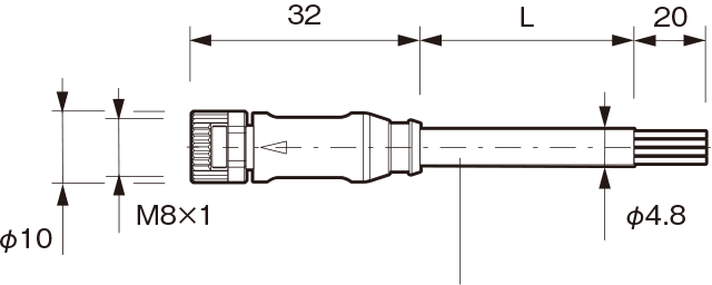
L = 2,000 (M84CN-2S)
L = 5,000 (M84CN-5S)
L = 10,000 (M84CN-10S)
Cable material: PVC
Lead wire: 4 cores x 0.25 mm2
Minimum bending radius
Cable diameter x 5 (when fixed in place)M84CN-2L, M84CN-5L, M84CN-10L
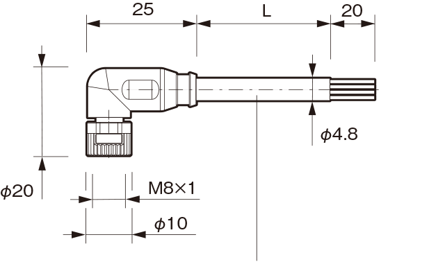
L = 2,000 (M84CN-2L)
L = 5,000 (M84CN-5L)
L = 10,000 (M84CN-10L)
Cable material: PVC
Lead wire: 4 cores x 0.25 mm2
Minimum bending radius
Cable diameter x 5 (when fixed in place)