Fiber-Optic SensorsD3RF/D3IF Series
Easy-to-use and low cost.
The 3rd generation of high-speed Fiber-Optic Sensors.
 Fastest high-speed response in the world
Supports cross talk prevention functions for up to 2 units, even in the fastest mode- New generation specifications for sensing distance as well
- 100% display for better recognition of level change

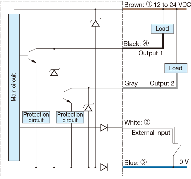
I/O circuit diagram
-
NPN output type
-
PNP output type
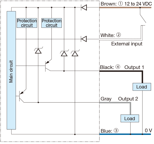
・Control output 2 (gray) is equipped only for dual-output types. In addition, power supply wires (brown/blue) are not equipped for inter-connection slave units.
-
Connector type
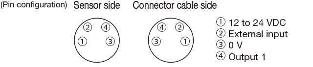
Connecting
▪ When not used for control output 2 or external input, cut the lead wire and wrap it individually with insulating tape, and do not connect it to any other terminal.
▪1 to 4 correspond to connector pin No. -
▪Notes
▪ When using a switching regulator for the power supply, be sure to ground the frame ground terminal.
▪ Because wiring sensor wires with high-voltage wires or power supply wires can result in malfunctions due to noise, which can cause damage, make sure to wire separately.
▪ Avoid using the transient state while the power is on (approx. 300 ms).
▪ The connector direction is set as in the diagram below when using the L-shaped connector cable. Be aware that rotation is not possible.
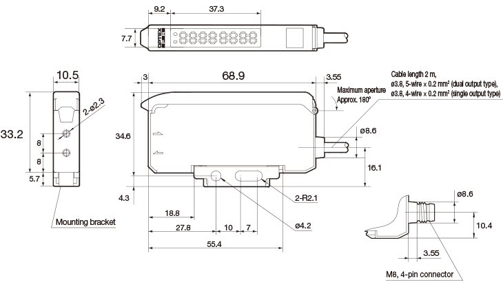
Dimensions
Stand-alone type
D3RF-TN, -TCN4, -TDN
D3RF-TP, -TCP4, -TDP
D3IF-TN, -TCN4, -TP, -TCP4
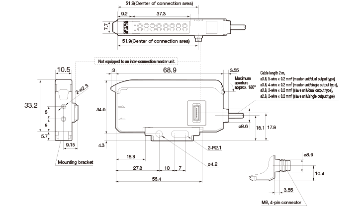
Inter-connection type
D3RF-TMN, -TMCN4, -TDMN
D3RF-TSN, -TSCN4, -TDSN
D3RF-TMP, -TMCP4, -TDMP
D3RF-TSP, -TSCP4, -TDSP
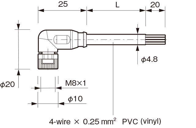
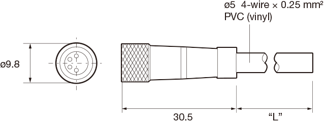
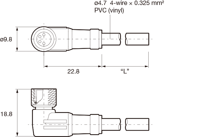
Connector cable (optional)
-
JCN-S, JCN-5S, JCN-10S
-
JCN-L, JCN-5L, JCN-10L
Successor models
M84CN-2S, M84CN-5S, M84CN-10S
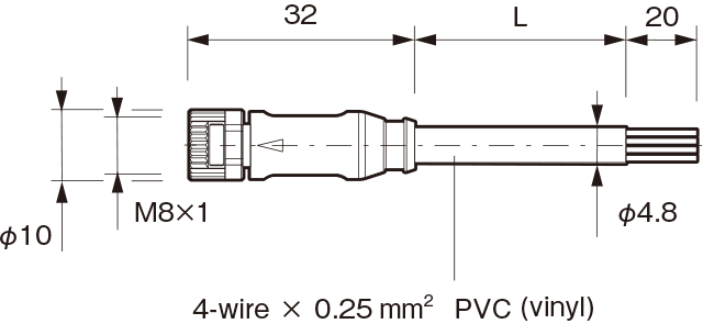
M84CN-2L, M84CN-5L, M84CN-10L