BGS Sensors with IO‑Link SupportZ4B Series
High‑power LED, with IO‑Link support
BGS sensors with a small-spot LED
- IO-Link support: Connectable to various field networks via IO-Link Master
- High-power and small-spot LED light source
- Enhanced ambient illuminance resistance
NEW MODELS
IR LED types added to the lineup

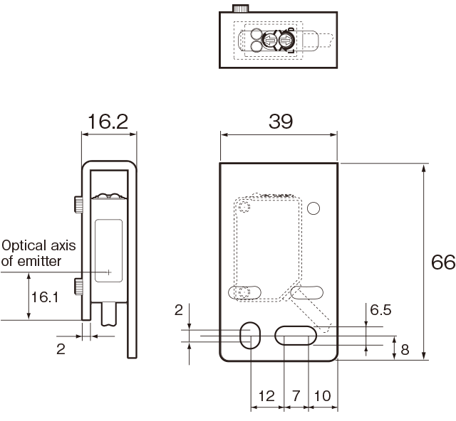
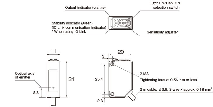
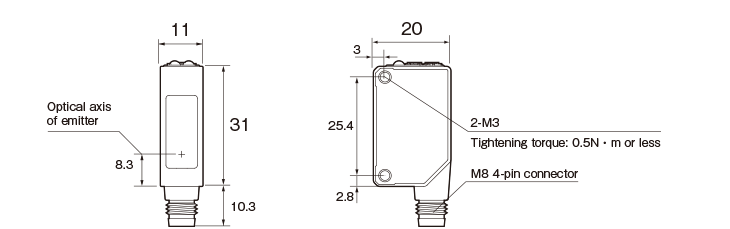
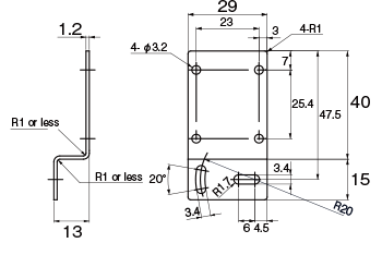
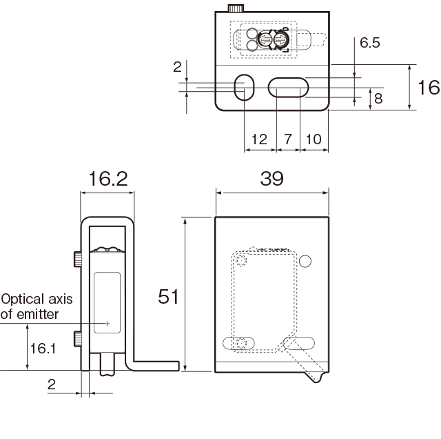
Dimensions
(Unit: mm)
Cable type
Connector type
Connector cable (option)
M84CN-2S, M84CN-5S, M84CN-10S
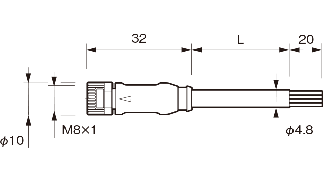
Cable material: PVC
Lead wire: 4 wires x 0.25 mm2
L = 2000 (M84CN-2S)
= 5000 (M84CN-5S)
= 10000 (M84CN-10S)
Minimum bending radius: R24 mm (when fixed in place)M84CN-2L, M84CN-5L, M84CN-10L
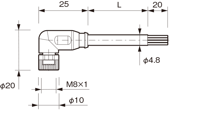
Cable material: PVC
Lead wire: 4 wires x 0.25 mm2
L = 2000 (M84CN-2L)
= 5000 (M84CN-5L)
= 10000 (M84CN-10L)
Minimum bending radius: R24 mm (when fixed in place)
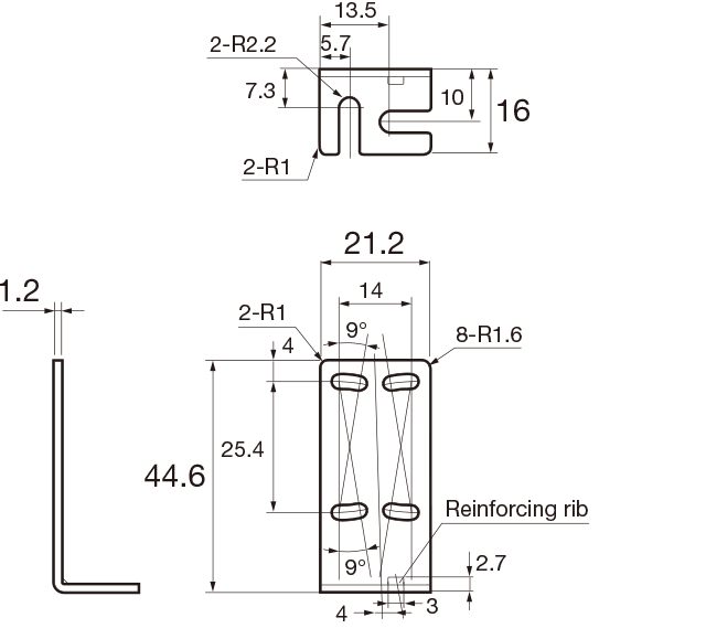
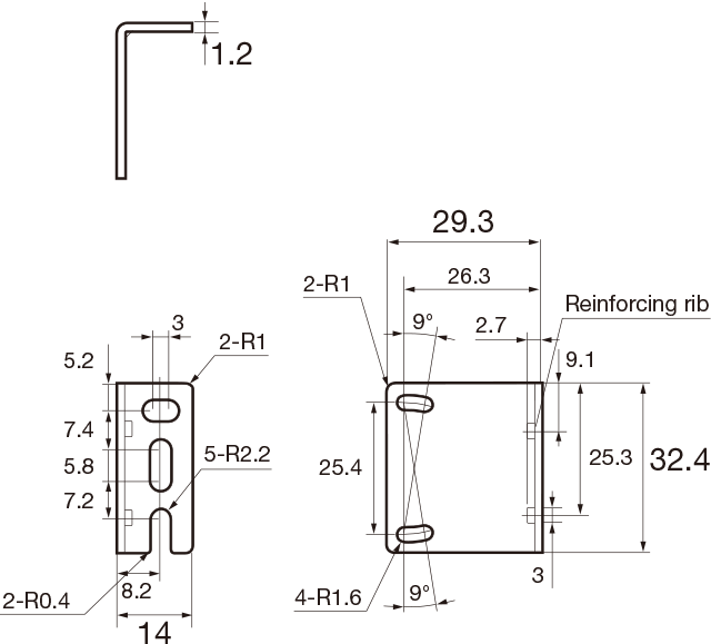
Mounting bracket (option)
-
BEF-W100-B: Floor-mounted for cable type
-
BEF-W100-A: Back-mounted for connector type
-
BEF-W100-C: Floor-mounted for cable type
Protective mounting bracket (for cable type)
-
LK-S01
-
LK-S02