


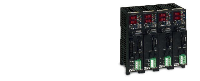
LED Lighting Controller AdvancedOPPF Series
Increased capacity with up to 48 W in PWM mode and up to 24 W in strobe mode
- “FALUX sensing” for monitoring brightness and temperature monitoring and for controlling feedback
- Support for RS232, parallel, and 0 to 5 V analog input for external dimming control
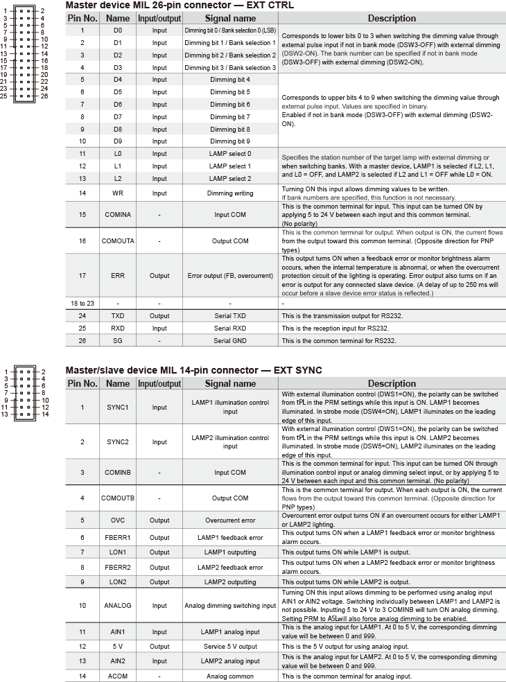
I/O Function List
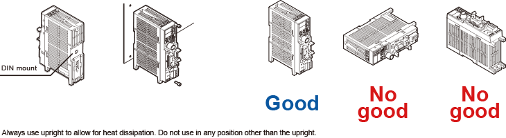
Installation
Installation examples
Rear DIN mounting or screw mounting is possible.
-
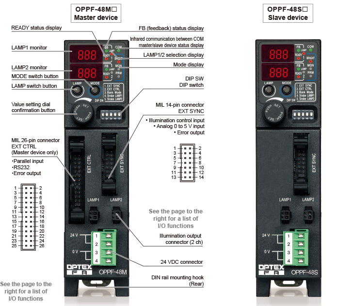
Master device: MIL 26-pin connector (EXT CTRL)
Master/slave device: MIL 14-pin connector (EXT SYNC)
[Optional cables]
MIL socket connector harness (type with one side trimmed)
28 AWG twisted-pair double-shielded cable
For master device, MIL 26-pin (3 m)
→ OP-ECBF26-3
For master/slave device, MIL 14-pin (3 m)
→ OP-ECBF14-3Note: Please use shielded cables in environments susceptible to noise.
-
Master/slave device: 24 VDC input (power source)
Applicable wiring: 0.2 to 2.1 mm2, 24 to 14 AWG
Coated strip length: 7 mm
Upper 2-pole: 24 VDC, Lower 2-pole: 0 V
Note: Use open terminals to pass power between units
with 1 pole per wire.