High-performance Multi-unit Laser Displacement SensorsCD5 Series
Next level integration of accuracy, stability, and operability
- Highest-in-class repeat accuracy and linearity
- 3 CH multi-calculation function is possible
- Measurement is possible using only the sensor head


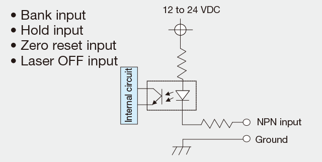
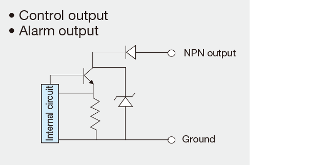
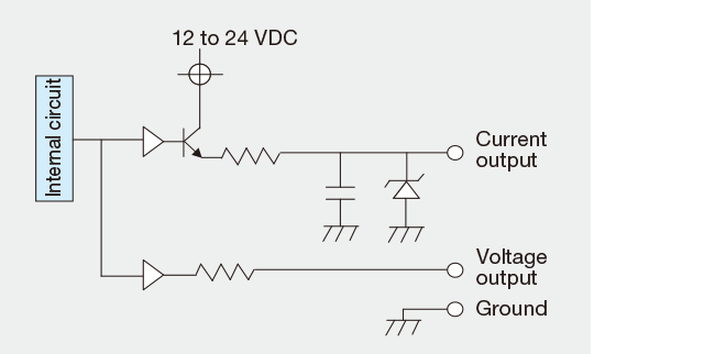
I/O circuit diagram and connections
-
Input circuit diagram (NPN)
-
Output circuit diagram (NPN)
-
Analog output circuit diagram
-
Input circuit diagram (PNP)
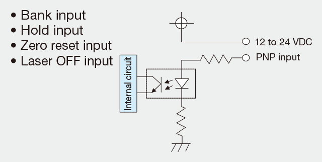
-
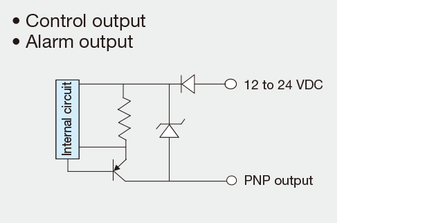
Output circuit diagram (PNP)
-
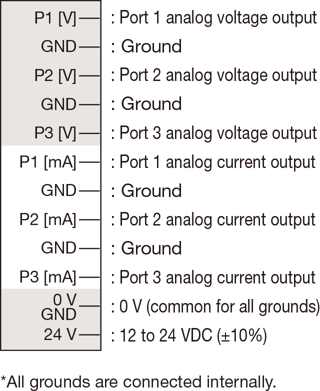
12-pin I/O terminal pin assignment
-
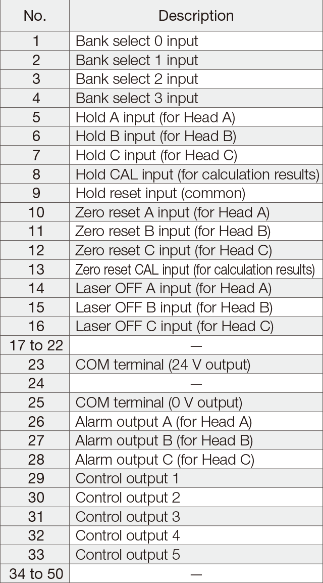
50-pin I/O terminal pin assignment
-
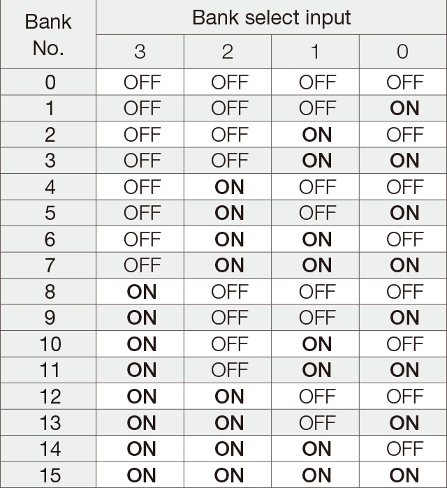
Bank select input
-
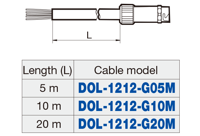
Sensor head cable wiring
(DOL-1212-G☐☐M)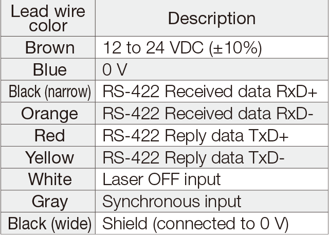
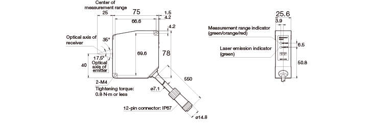
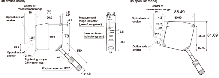
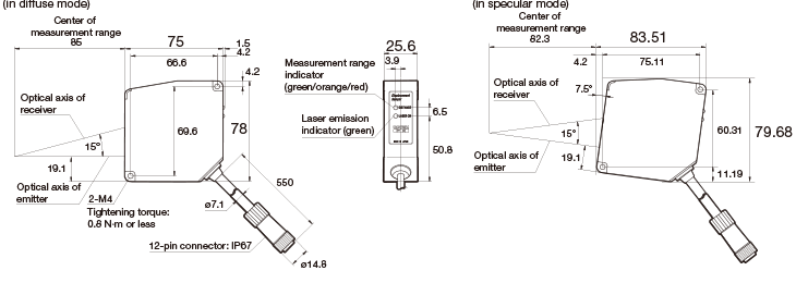
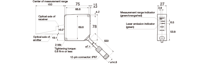
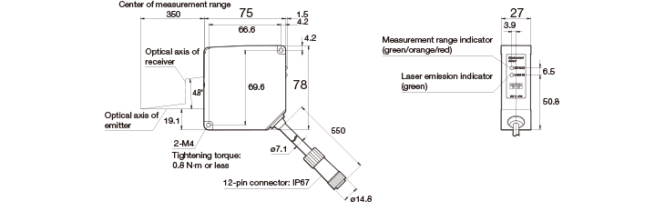
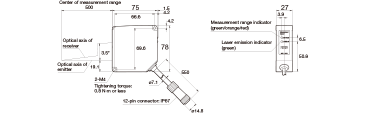
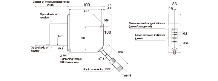
Dimensions
Sensor head
CD5-L25A/-LW25A
CD5-30A/-W30A
CD5-85/-W85
CD5-150/-W150
CD5-W350
CD5-W500
CD5-W2000
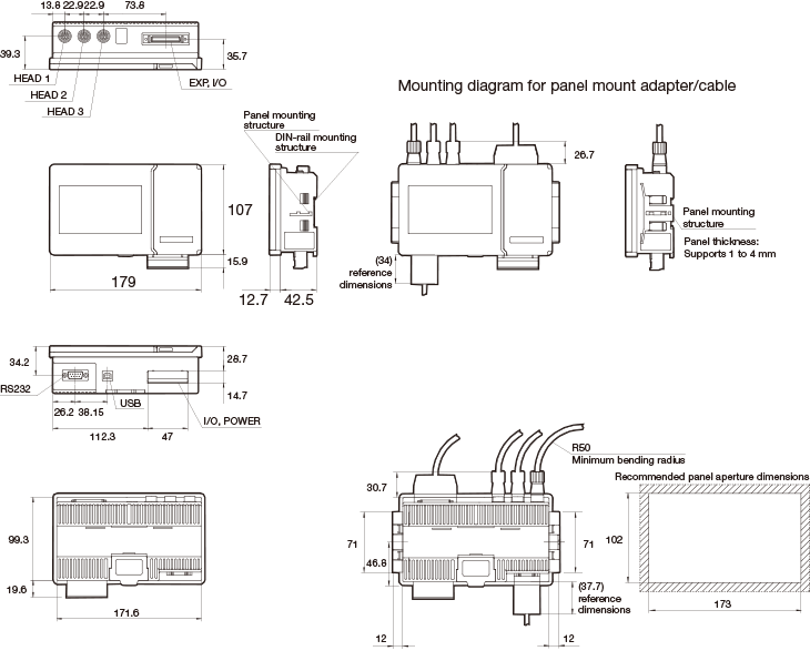
Amplifier unit
CD5A-☐
-
Extension cable between sensor head
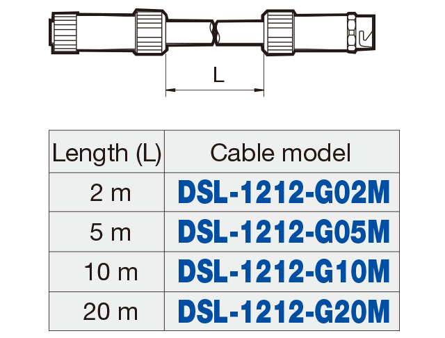
-
Sensor head cable
-
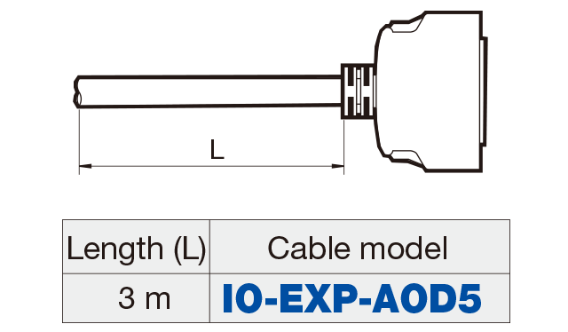
I/O connection cable
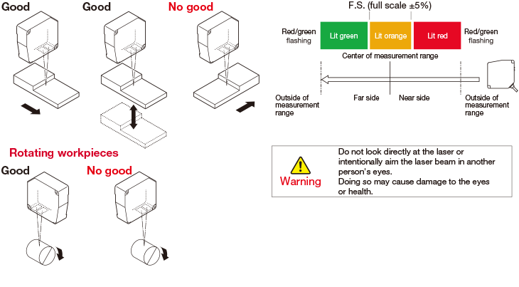
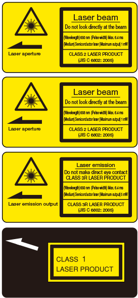
Precautions for laser use
-
This product emits a Class 1/Class 2 (II) or Class 3R (IIIa) visible laser beam that is compliant with JIS C 6802/IEC/FDA laser safety standards.
Because English language warnings indicating the sensor as Class 1 or Class 2 (II) or Class 3R (IIIa), as well as explanation labels, are located on the side of the sensor, please replace these warnings/explanation labels with the Japanese language warnings/ explanation labels included in the box when using in Japan.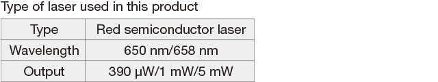
If you install this product in a piece of machinery that will then be exported to the United States, it is necessary to follow laser standards as stipulated by the American Food and Drug Administration (FDA).
This product has already been submitted to the CDRH (Center for Devices and Radiological Health). (Please inquire for details.) -

Workpieces with large fluctuations in height difference or color
Mount the sensor head so that the detection surface (emitting/receiving part surfaces) is always parallel to the detection target. Adjust the target so that the spot aligns with the detection position, and ensure that the distance indicator lights up orange at the reference window (center of change).