Digital Fiber Sensor D3WF (White LED)
Compact Laser Displacement Sensor CD22
Through-beam Edge Sensor TD1
Features
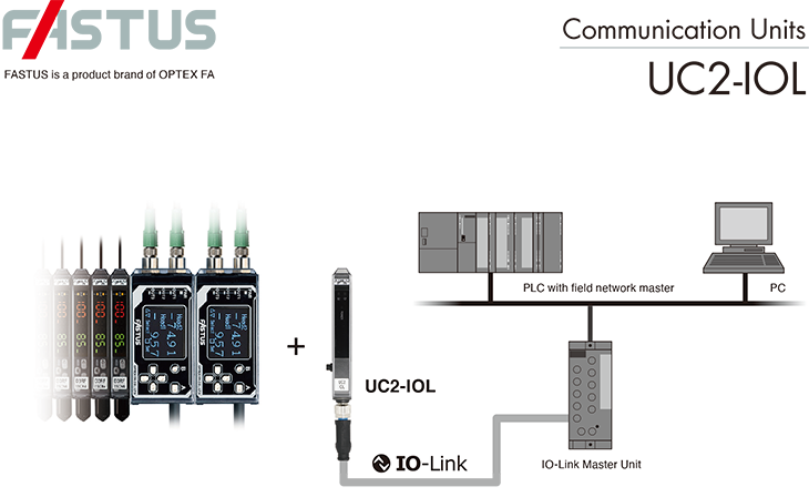
● Gateway unit to connect sensors to IO-Link network
● Compact interface to save space and channels on IO-Link Master unit
● Max. 16 units of D3RF/D3WF fiber sensor amplifier or 8 units of CDA
displacement sensor amplifier can be connected.
● Compact interface to save space and channels on IO-Link Master unit
● Max. 16 units of D3RF/D3WF fiber sensor amplifier or 8 units of CDA
displacement sensor amplifier can be connected.
Sharable Device/Module Data via IO-Link Network
| Data | D3RF | D3WF | CD22*1 | TD1*1 | UC2 |
|---|---|---|---|---|---|
| Cyclic Communication | |||||
| Measurement Value*2 | Read: Light amount | Read: Light amount | Read: Distance | Read: Distance | - |
| Output 1*2 | Read | Read | Read*3 | - | - |
| Output 2*2 | Read | - | Read*3 | - | - |
| Acyclic Communication | |||||
| Device status | Read | Read | Read | Read | Read |
| Measurement mode | - | - | Read/Write | Read/Write | - |
| Threshold | Read/Write | Read/Write | Read/Write | Read/Write | - |
| Hysteresis | Read/Write | Read/Write | Read/Write | Read/Write | - |
| Calculation | - | - | Read/Write: Mode, Offset |
Read/Write: Mode, Offset |
- |
| Averaging | - | - | Read/Write | Read/Write | - |
| Response time / Sampling speed |
Read/Write | Read/Write | Read/Write | Read/Write | - |
| Output mode & polarity | - | - | Read/Write | Read/Write | - |
| Timer mode & setting | Read/Write | Read/Write | - | - | Read/Write |
*1 : via CDA unit
*2 : Max. combination of 13 variables and 32 control outputs of 16 modules, 14 variables and 28 control outputs of 14 modules or 16 variables of 16 modules.
*3 : per CDA unit
Specifications
| Model | UC2-IOL | |
|---|---|---|
| IO-Link Specification*1 | Min. cycle time | 2.2 ms |
| Transmission rate | COM3 (230.4kbps) | |
| ISDU Support | Yes | |
| IO-Link Version | 1.1 | |
| Process input data byte | 32 bytes | |
| Process output data byte | 0 byte | |
| IO-Link frame type | F-Sequence Type 2.V | |
| Connectable device | Connectable models | D3RF/D3WF series inter-connection master and slave unit CDA series master unit and slave unit |
| No. of connectable units | Up to 16 units*2 (One CDA unit requires two spaces) | |
| Indicator | Power (Green) SIO: Constant, IO-Link: Blinking Output×2 (Orange) |
|
| Rating | Supply voltage | SIO: 12 to 24 VDC including 10% of ripple (P-P) IO-Link: 18 to 24 VDC including 10% of ripple (P-P) (SELV and LIM or Class 2)*3 |
| Current consumption | 40mA Max.*4 | |
| Control output | Push-Pull × 2 ch Max.100mA/24VDC (Sum of 2 ch) Residual voltage 1.8 V Max. |
|
| External input | Teaching input / Smart task input | |
| Connection | M8 4-pin male connector | |
| Protection circuit | Reverse connection protection, Overcurrent protection | |
| Environmental resistanc | Installation location | Indoor use |
| Ambient temperature/humidity | -25 to +55°C / 35 to 85% RH (no freezing or condensation) | |
| Storage temperature/humidity | -40 to +70°C / 35 to 95% RH | |
| Vibration resistance | 10 to 55 Hz; double amplitude 1.5 mm; 2 hours in each of the X, Y, and Z directions | |
| Shock resistance | 500 m/s2 (approx. 50 G), 3 times in each of the X, Y, and Z directions | |
| Degree of protection | IP 50 (According to IEC 60529) | |
| Pollution degree | IEC 60664-1:2007 Pd2 | |
| Operating altitude | Up to 2000m above sea level | |
| Noise resistance | Feilen level 3 | |
| Applicable regulation | EMC | EMC directive(2014/30/EU) |
| Environment | RoHS directive(2011/65/EU) China RoHS (Directive 32) | |
| NRTL Certification | UL Listed (in process) | |
| Applicable standards | EN 60947-5-2 | |
| Weight | Approx. 16g | |
| Material | Case, protective cover: PC | |
| Included accessory | Instruction manual | |
*1. Index list and IODD file can be downloaded from www.optex-fa.com.
*2. The maximum number of connectable units varies depending on the ambient temperature.
| Series | D3RF/D3WF | CDA-M+CDA-S | CDA-DM2+CDA-S | |||
| Ambient temperature | -25 to +55℃ | -25 to +50℃ | -25 to +45℃ | -25 to +50℃ | -25 to +50℃ | -25 to +45℃ |
| No. of connectable units | 1 to 3 | 4 to 8 | 9 to 16 | 1 to 8 | 1 | 2 to 8 |
*3. Use a Class 2 power supply or a power supply that conforms to the SELV circuit (Safety Extra-Low Voltage) and the LIM circuit (Limited Energy Circuit).
*4. Not including control output load current.
Accessories
-
Connector cables
Model Description M84CN-2S Straight, M8 4-pin, 2 m M84CN-5S Straight, M8 4-pin, 5 m M84CN-10S Straight, M8 4-pin, 10 m 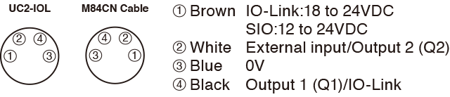
-
End plate
Model Description BEF-EB01-W190 Delivered in 2 pieces
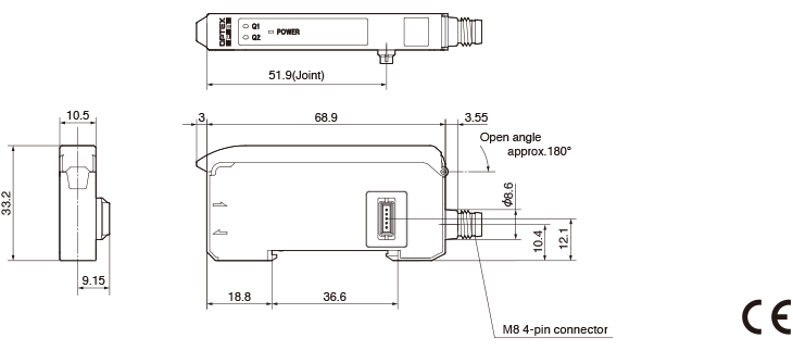
Dimensions
(Unit : mm)