


Ultra High-Accuracy Laser Displacement SensorsCDX Series
World’s No. 1 Linearity
- Developed image sensor: ATMOS
- Direct Ethernet connection
- Equipped with a Web Server


System Configuration
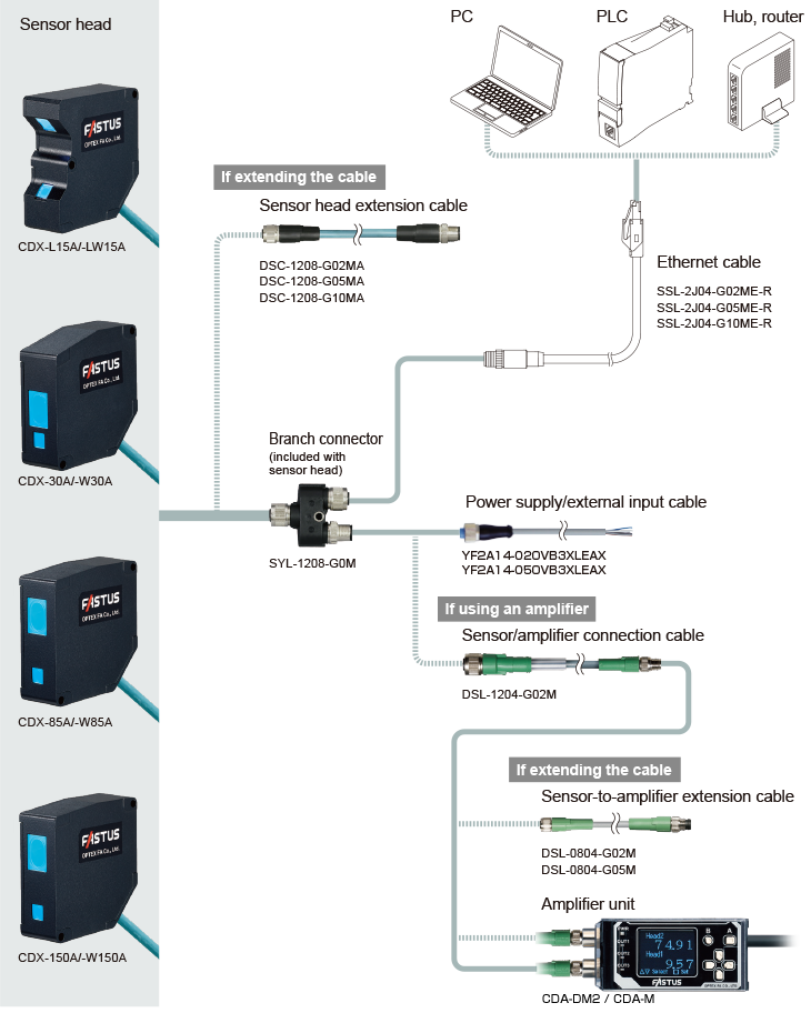
○ Ensure that the overall cable length from the power supply to the sensor head is within 30 m, and the number of Sensor Head Extension Cables to be connected must be up to two.
Also ensure that the overall cable length when the CDA series amplifier unit is used is within 10 m.
(This length restriction does not apply to the Ethernet cable.)
Options
Connectors/Connector CablesDiscontinued and successor models of connector cables
-
Sensor head
extension cable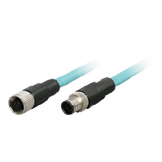
Dedicated cable for extension between the sensor head and branch connector.
Extension up to 20 m is possible.
Robot cable specifications.
• Sensor side: M12, 8-pin socket
• Branch connector side: M12, 8-pin plugDSC-1208-G02MA
2m
DSC-1208-G05MA
5m
DSC-1208-G10MA
10m
-
Ethernet cable
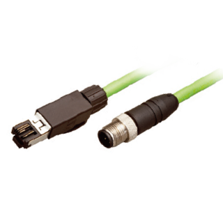
Dedicated cable for connecting from the branch connectors to the Ethernet port.
Robot cable specifications.
• Branch connector side: M12, 4-pin plug
• Host side: RJ45 plugSSL-2J04-G02ME-R
2m
SSL-2J04-G05ME-R
5m
SSL-2J04-G10ME-R
10m
-
Power supply/
external input cable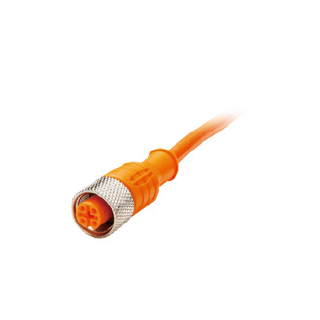
Power supply/external input cable for connecting to branch connector.
• Branch connector side: M12, 4-pin socket
• Power supply/external device side: discrete wireDOL-1204-G02M
2m
DOL-1204-G05M
5m
-
Power supply/
external input cable
Successor models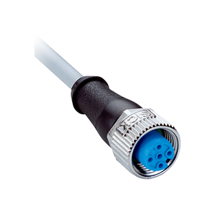
Power supply/external input cable for connecting to branch connector.
• Branch connector side: M12, 4-pin socket
• Power supply/external device side: discrete wireYF2A14-020VB3XLEAX
2m
YF2A14-050VB3XLEAX
5m
-
Branch connector
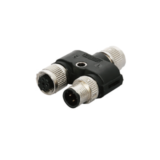
Branch connector for connecting sensor heads and various cables.
Included with sensor head.SYL-1208-G0M
-
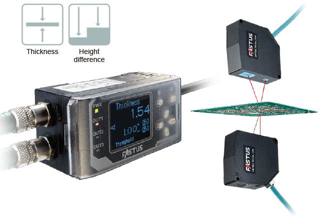
Displacement sensor amplifier unit CDA series
The CDA series amplifier unit is equipped with an organic EL display on which both Japanese characters and English lettering can be viewed with clarity. Control can be performed using either analog or control outputs, while thickness and height difference measurements can be performed using two sensor heads.
-
| Type | 1 × analog output 2 × external inputs 3 × control outputs |
2 × high-resolution analog outputs 1 × external input 2 × control outputs |
||
|---|---|---|---|---|
| Main unit | Expansion unit | Main unit | ||
| Model | CDA-M | CDA-S | CDA-DM2 | |
| Sensor head (CDX Series) |
Number of connectable sensors | Max. 2 sensors per CDA unit | ||
| Connection type | Amplifier side: M8, 4-pin connector | |||
| Communication I/F | RS-485 compliant (Overall cable length: Within 10m) | |||
| Rating | Supply voltage | 12 to 24 VDC ±10%, including 10% ripple (p-p) | Supplied from the main unit or UC1/UC2 *1 | 12 to 24 VDC ±10%, including 10% ripple (p-p) |
| Current consumption | 100 mA or less (at 12 V) |
100 mA or less (at 12 V) |
120 mA or less (at 12 V) |
|
| Display | Dot matrix display | OLED 128 x 96 pixels | ||
| Indicators | Power indicator (PWR): red/green, output indicators (OUT1/OUT2/OUT3): orange |
|||
| Analog output | No. of outputs | 1 | 1 | 2 |
| Type | 4 to 20 mA: Load impedance; 300 Ω or less |
4 to 20 mA: Load impedance; 300 Ω or less |
4 to 20 mA: Load impedance; 300 Ω or less 0 to 10 V: Output impedance; 100 Ω (selectable by setting) |
|
| Control output | No. of outputs | 3 | 3 | 2 |
| Type | NPN/PNP open collector (selectable by setting) Max. 100 mA/30 VDC, Residual voltage: 1.8 V or less |
|||
| External input | 2 inputs | 2 inputs | 1 input | |
|
Environmental resistance |
Ambient temperature/humidity | -20 to +50℃ / 35 to 85% RH (no freezing or condensation) | ||
| Storage temperature/humidity | -20 to +60℃ / 35 to 85% RH (no freezing or condensation) | |||
| Vibration resistance | 10 to 55 Hz; double amplitude 1.5 mm; 2 hours in each of the X, Y, and Z directions |
|||
| Shock resistance | Approx. 50 G (500 m/s2), 3 times in each of the X, Y, and Z directions |
|||
| Protection circuit | Reverse connection protection, overcurrent protection | |||
| Degree of protection | IP50 (IEC 60529) | |||
| Applicable regulations |
EMC | EMC directive (2014/108/EU) | ||
| Environment | RoHS directive (2011/65/EU), China RoHS (Directive No. 32) | |||
| Applicable standards | EN 60947-5-7 | |||
| NRTL Certification | UL Recognized Components | |||
| Material | Polycarbonate | |||
| Weight (including cable) | Approx. 170 g | |||
*1: Supply 12 to 24 VDC to the power wires (brown and blue) of the cable as the supply voltage for the compatible sensors.
• CDA-DM models have been discontinued. Please use the CDA-DM2 successor model. Click here for more information.
●If using an amplifier unit, some settings for the CDX series cannot be confirmed or changed. For details, see the CDX series user's manual.
●On the CDX series, CH1 is the only output that can be set and used with an amplifier unit.
●The CDX series does not support CC-Link communication.
●The resolution of the analog outputs (shown below tables) will be lower than that when using Ethernet communication. CDA-DM2 can achieve the same resolution as Ethernet communication by using the scaling function to narrow the measurement range.
CDA-DM2 with analog volatage output
-
Measurement Scale Analog Output Scale Model Measurement Range Resolution Measurment range Resolution CDX-L15A/-LW15A +/-1.0mm 0.25μm +/-1.0mm 0.25μm CDX-30A/-W30A +/-5.0mm 0.25μm +/-5.0mm 0.25μm CDX-85A/-W85A +/-20.0mm 0.68μm +/-7.375mm 0.25μm CDX-150A/-W150A +/-40.0mm 1.36μm +/-7.375mm 0.25μm
CDA-DM2 with analog current output
-
Measurement Scale Analog Output Scale Model Measurment range Resolution Measurment range Resolution CDX-L15A/-LW15A +/-1.0mm 0.25μm +/-1.0mm 0.25μm CDX-30A/-W30A +/-5.0mm 0.25μm +/-5.0mm 0.25μm CDX-85A/-W85A +/-20.0mm 0.93μm +/-5.375mm 0.25μm CDX-150A/-W150 A+/-40.0mm 1.86μm +/-5.375mm 0.25μm
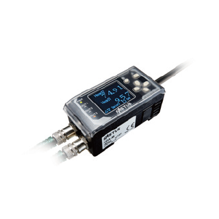
CDA-M
-
Model Resolution CDX-L15A/-LW15A +/-1.0μm CDX-30A/-W30A CDX-85A/-W85A +/-10.0μm CDX-150A/-W150A
Amplifier unit, connector cables for amplifier unit
-
Amplifier unit
An amplifier unit to which up to two sensor heads can be connected.
Control can be performed using either analog or control outputs, while thickness and height difference measurements can be performed using two sensor heads.Dual analog output type
CDA-DM2
2m
CDA-M
2m
-
Sensor/amplifier
connection cable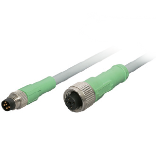
Connector cable for connecting branch connectors and amplifier units.
Robot cable specifications.
• Branch connector side: M12, 5-pin socket
• Amplifier unit side: M8, 4-pin plugDSL-1204-G02M
2m
-
Sensor-to-amplifier
extension cable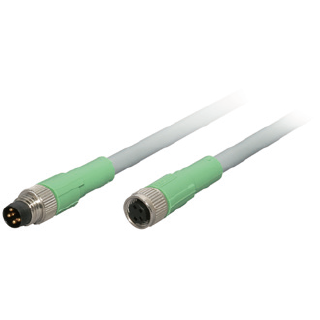
Extension cable for connection to DSL-1204-G02M.
Robot cable specifications.
• Sensor/amplifier connection cable side: M8, 4-pin socket
• Amplifier unit side: M8, 4-pin plugDSL-0804-G02M
2m
DSL-0804-G05M
5m