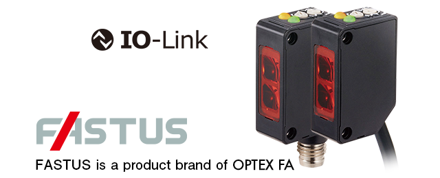
Standard-sized Built-in Amplifier SensorsZ4 Series
Industry standard sensors with IO-Link support
- Industry standard-sized amplifier built-in sensors
- IO-Link support: Connectable to various field networks via IO-Link Master
- Enhanced ambient illuminance resistance
NEW MODELS
Wide-angle diffuse-reflective types added to the lineup


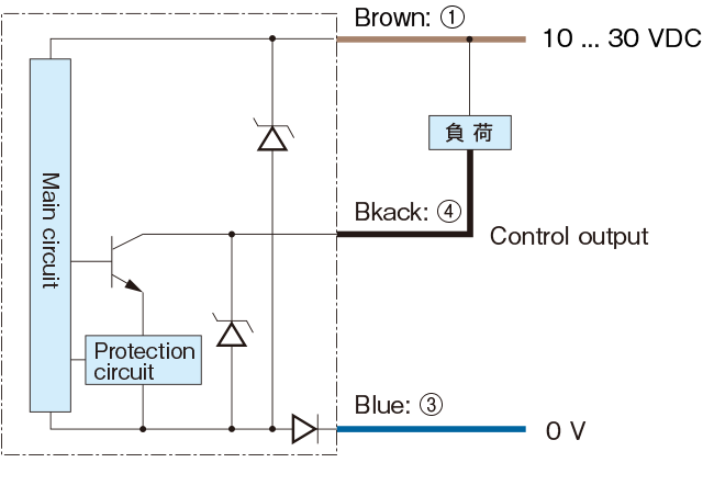
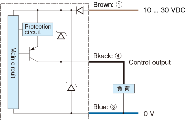
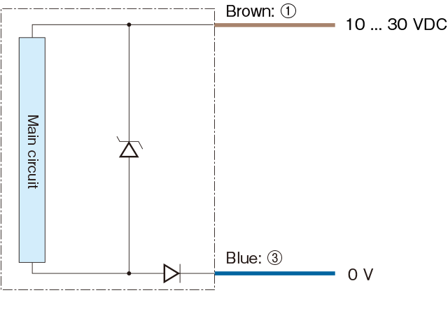
I/O Circuit Diagrams
-
IO-Link mode*
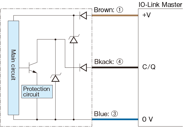
* When using NPN type for an IO-Link connection, use OPTEX FA’s IO-Link Master UR Series or IO-Link Master with sink support.
-
NPN type
-
PNP type
-
Through-beam type emitter
-
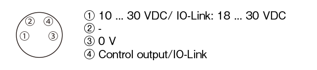
M8 connector pin assignments
-
Connecting
▪1 to 4 are connector pin No.
Notes
▪ When using a switching regulator for the power supply, be sure to ground the frame ground terminal.
▪ Because wiring sensor wires with high-voltage wires or power supply wires can result in malfunctions due to noise, which can cause damage, make sure to wire separately.
▪ Avoid using the transient state while the power is on (Approx. 250 ms).
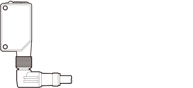
▪ The connector direction is fixed as the drawing below when you use L-shaped connector cable. Be aware that rotation is not possible.