Fiber-Optic CablesNF Series Sleeve/Side view type
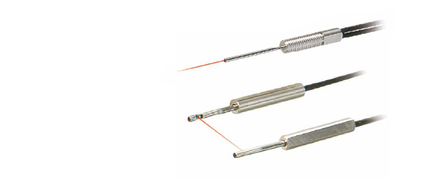
The fine tip makes mounting highly flexible
and adjusting position very easy
- Long sleeve type can be bent (Straight view type)
- Side angle light beam provides optimal detection in narrow places (Side view type) NF-TV01-5: End of sales by April 2026
Mounting method
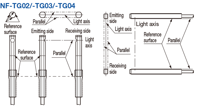
NF-TG02/-TG03/-TG04
・Please be aware that because the aperture angle of this product is extremely narrow, light may not be taken in depending on installation conditions.
Through-beam type
・When installing, determine a reference surface as shown in the diagram below while paying sufficient attention in regards to light axis shifting and slanting. Install so that emitting/receiving fibers are parallel.