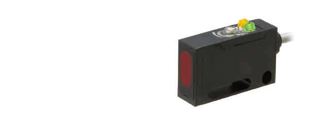
Resin-filled SensorsJ Series
Water resistant/vibration resistant resin filled and robust body
- Passed 100-hour test for water and oil resistance
- Achieved a level of vibration resistance far above that of JIS standards
- Mounting hole pitch: 10 to 25.4 mm
 Some models: End of sales by April 2026
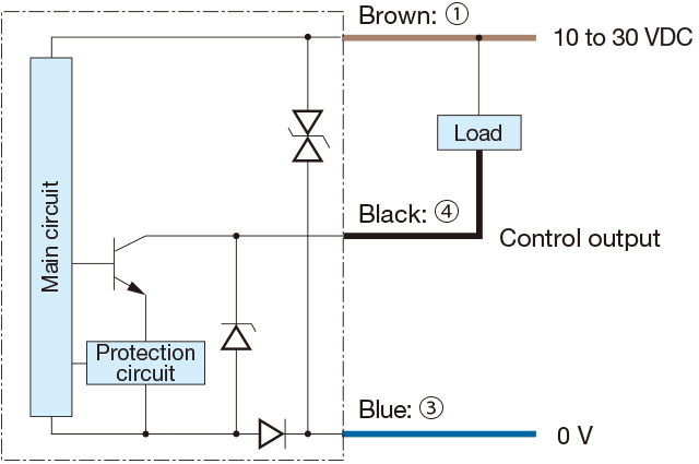
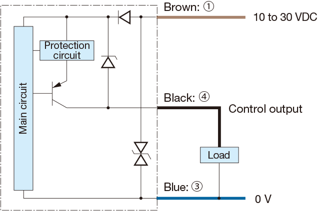
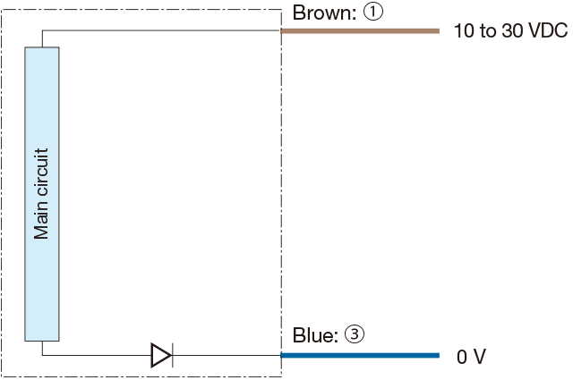
Output circuit diagram
-
NPN output type
-
PNP output type
-
Through-beam type emitter
-
Connector type
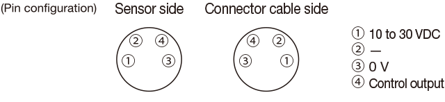
Connecting
▪1 to 4 are connector pin No.
Notes
▪ When using a switching regulator for the power supply, be sure to ground the frame ground terminal.
▪ Because wiring sensor wires with high-voltage wires or power supply wires can result in malfunctions due to noise, which can cause damage, make sure to wire separately.
▪ Avoid using the transient state while the power is on (approx. 100 ms).
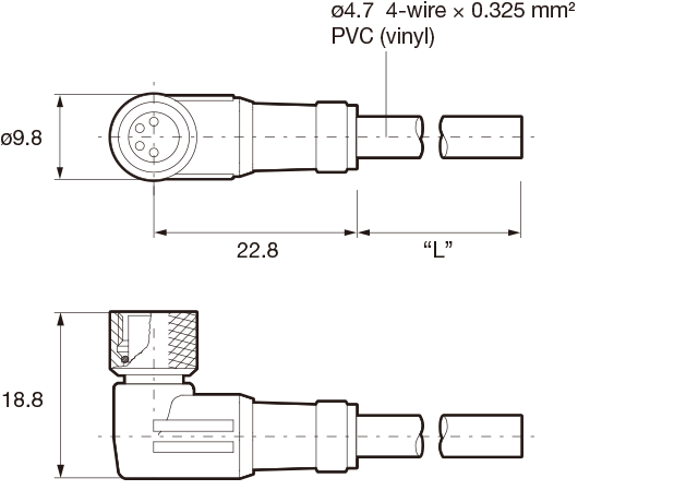
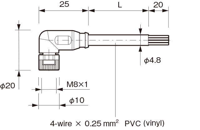
▪ The connector direction is fixed as the drawing below when you use L-shaped connector cable. Be aware that rotation is not possible.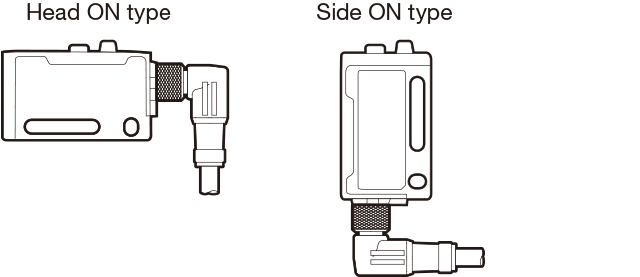
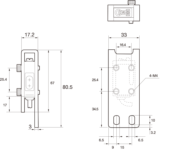
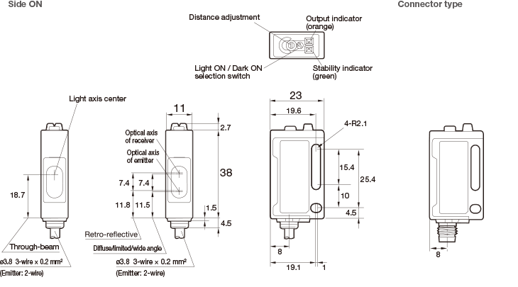
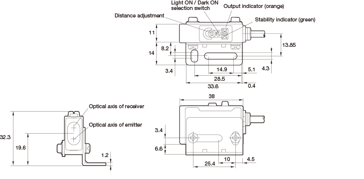
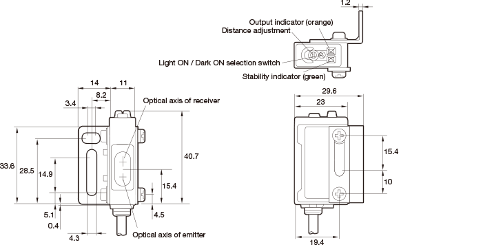
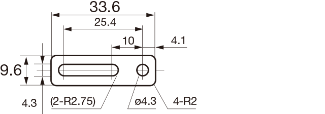
Dimensions
Unit : mm
Sensor
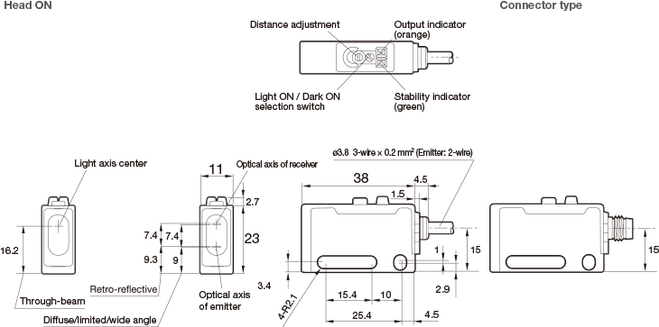
*Tighten to each of the sensor mounting holes with a torque of 0.5 N・m or less.
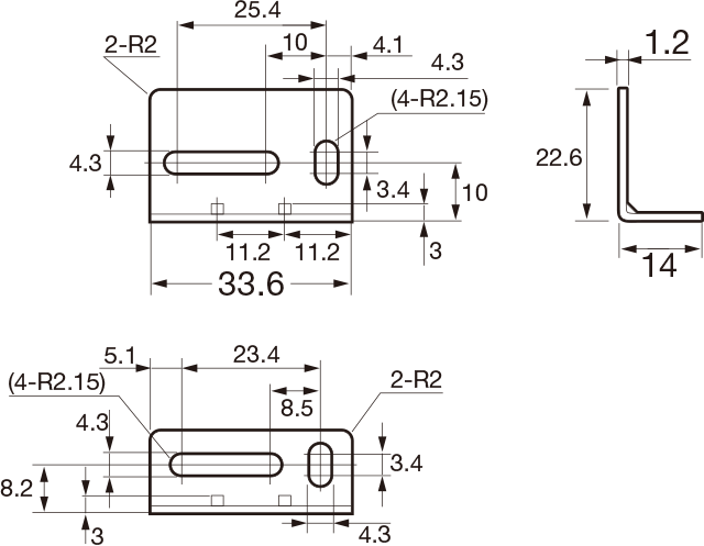
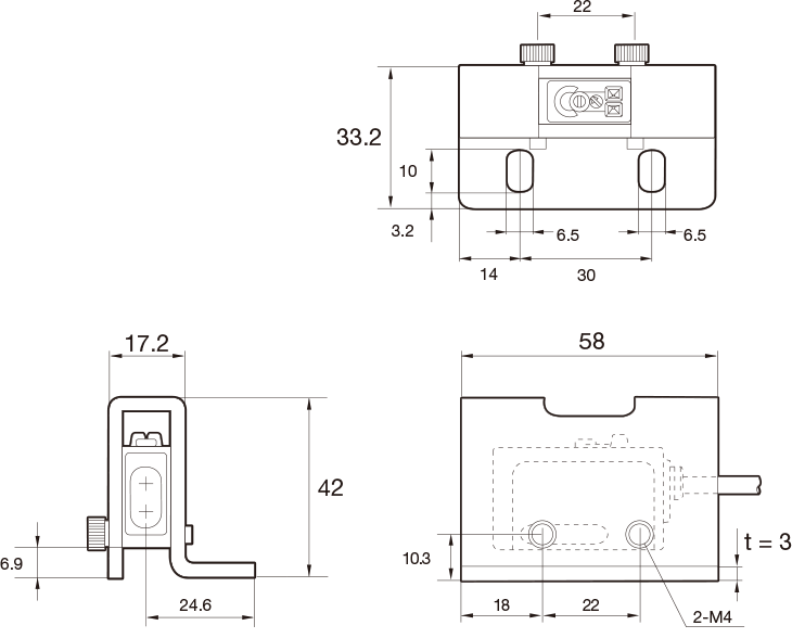
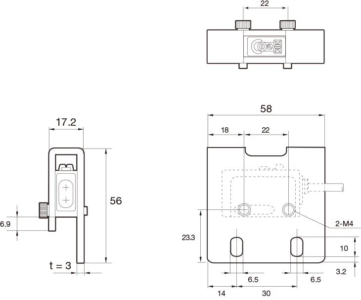
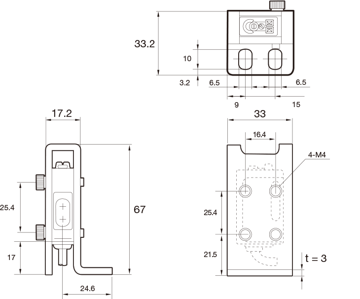
Mounting bracket
Head ON
Side ON
-
Mounting bracket (included)
BEF-W160
-
Nut plate
Included with BEF-W160 t = 1.2 mm
Connector cable (optional)
-
JCN-S, JCN-5S, JCN-10S
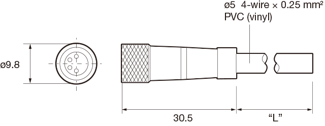
-
JCN-L, JCN-5L, JCN-10L
Successor models
M84CN-2S, M84CN-5S, M84CN-10S
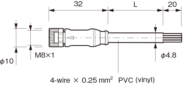
M84CN-2L, M84CN-5L, M84CN-10L
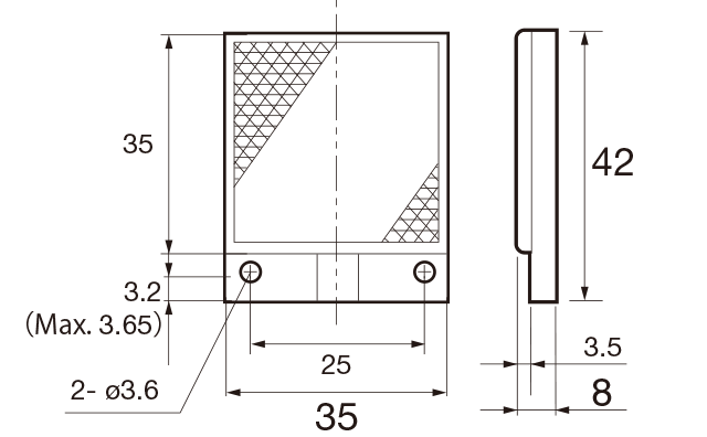
Reflector
-
V-61: Standard type reflector
(included with retro-reflective type)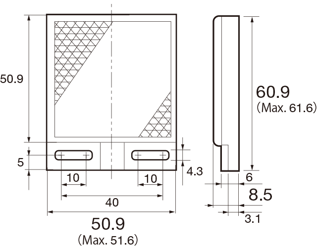
-
V-42: Small reflector (optional)
-
P45A: Vertical type reflector (optional)
DOL-1204-G02M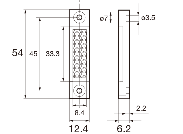
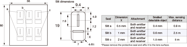
Slit mask
BL-160-SK: Slit mask (optional)
Protective mounting bracket (optional)
LJ-H01 (for Head ON)
LJ-H02 (for Head ON)
LJ-S01 (for Side ON)
LJ-S02 (for Side ON)