


Multifunction LED Lighting ControllerOPPX Series
Full support for image inspection
with multifunctionality
and lighting brightness control
- Support for 12 V and 24 V input lighting
- Support for Mitsubishi Electric iQSS
- Recognition of individual lighting and monitoring/feedback by the new technology FALUX sensing +


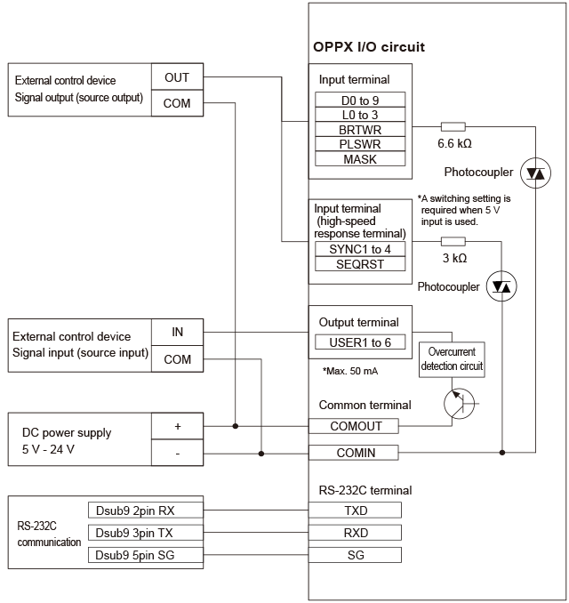
Connection to external device
-
NPN connection (sink connection)
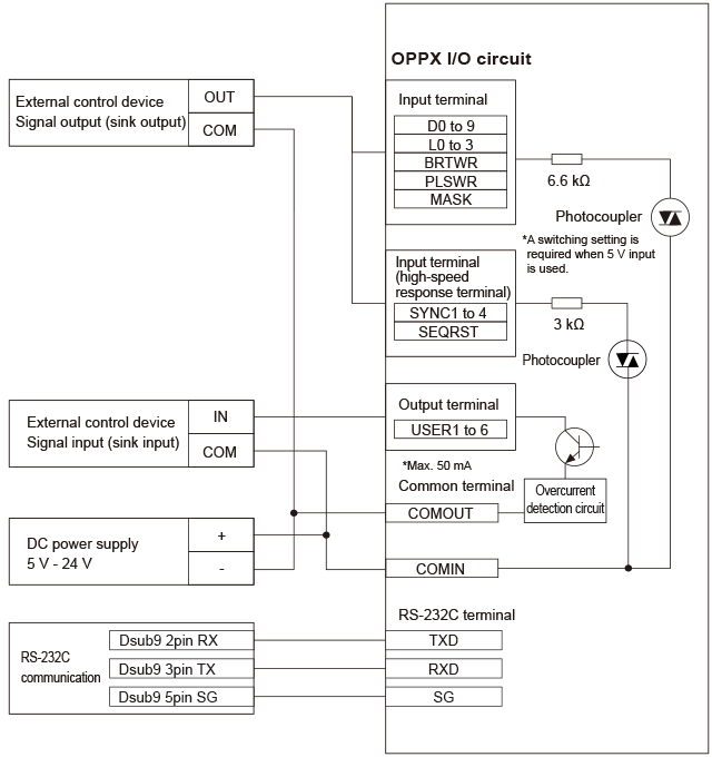
-
PNP connection (source connection)
I/O function list
-
External illumination control connector (included accessory)
Compatible wire: 0.2 to 1.3 mm2, AWG 24 to 16
Length of stripping part: 9 to 10 mm, Terminal specification: Push-in
Dedicated cable model: OP-ECBX9-3 (sold separately) -
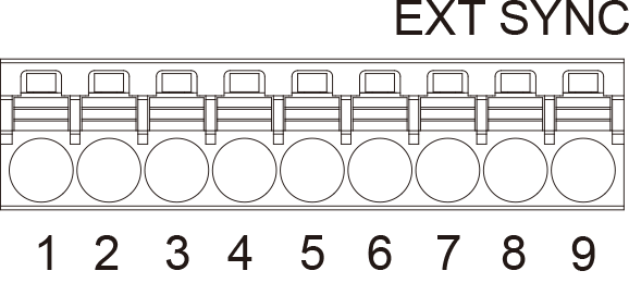
Pin assignment
| Pin No. | Name | Input/ output |
Signal name | Explanation of signal name |
|---|---|---|---|---|
| 1 | SYNC1 | Input | External synchronization input 1 | The lamp illuminates while this input is ON. When the illumination time is specified, the lamp illuminates for the specified time following brightness rise. The subject lamp can be selected via the settings. |
| 2 | SYNC2 | Input | External synchronization input 2 | |
| 3 | SYNC3 | Input | External synchronization input 3 | |
| 4 | SYNC4 | Input | External synchronization input 4 | |
| 5 | SEQRST | Input | Sequence reset input | Not used for external synchronization control. |
| 6 | COMINB | − | Input COM | This is the input common terminal. Each input can be turned ON by applying 5 - 24 V between the input and this common terminal. (No polarity) |
| 7 | USER1 | Output | Multi-function output 1 | This is a multi-function output pin. It is possible to set the output contents. It is the same as USER1 on the external parallel connector. |
| 8 | USER2 | Output | Multi-function output 2 | This is a multi-function output pin. It is possible to set the output contents. It is the same as USER2 on the external parallel connector. |
| 9 | COMOUTB | − | Output COM | This is the output common terminal. When output is ON, current flows from the output to this common terminal. |
-
External parallel connector
Applicable connector: HIROSE FX2-32PA insulation-displacement connector with lock
Dedicated cable model: OP-ECBX32-3 (sold separately) (open-ends at one end: 3 m) -
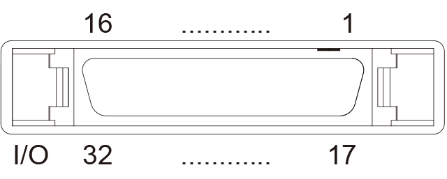
| Pin No. | Name | Input/ output |
Signal name | Explanation of signal name |
|---|---|---|---|---|
| 1 | D0 | Input | Light intensity bit 0 | Inputs the light intensity value or the illumination time. Writing is performed using the BRTWR or PLSWR signal in combination with the specified station number. The recipe number can also be switched by changing the input mode. |
| 2 | D1 | Input | Light intensity bit 1 | |
| 3 | D2 | Input | Light intensity bit 2 | |
| 4 | D3 | Input | Light intensity bit 3 | |
| 5 | D4 | Input | Light intensity bit 4 | |
| 6 | D5 | Input | Light intensity bit 5 | |
| 7 | D6 | Input | Light intensity bit 6 | |
| 8 | D7 | Input | Light intensity bit 7 | |
| 9 | D8 | Input | Light intensity bit 8 | |
| 10 | D9 | Input | Light intensity bit 9 | |
| 11 | L0 | Input | LAMP switching 0 | Specifies the lamp station number for performing light intensity adjustment. The value is specified in binary. |
| 12 | L1 | Input | LAMP switching 1 | |
| 13 | L2 | Input | LAMP switching 2 | |
| 14 | L3 | Input | LAMP switching 3 | |
| 15 | BRTWR | Input | Light intensity value writing | Writes the light intensity bit as the light intensity value (or recipe number). |
| 16 | COMINA | − | Input COM | This is the input common terminal. Each input can be turned ON by applying 5 - 24 V between the input and this common terminal. (No polarity) |
| 17 | RXD | Input | RS-232C receive data | This is the RS-232C receive data. |
| 18 | TXD | Output | RS-232C transmit data | This is the RS-232C transmission output. |
| 19 | SG | − | RS-232C signal ground | This is the RS-232C common terminal. |
| 20 | PLSWR | Input | Illumination time write | Writes the light intensity bit as the illumination time. |
| 21 | MASK | Input | Writing mask | When ON, controls the write signal (BRTWR, PLSWR) input. |
| 22 | USER1 | Output | Multi-function output 1 | This is a multi-function output pin. It is possible to set the output contents. It is the same as external illumination control connector USER1. |
| 23 | USER2 | Output | Multi-function output 2 | This is a multi-function output pin. It is possible to set the output contents. It is the same as external illumination control connector USER2. |
| 24 | USER3 | Output | Multi-function output 3 | This is a multi-function output pin. It is possible to set the output contents. |
| 25 | USER4 | Output | Multi-function output 4 | |
| 26 | USER5 | Output | Multi-function output 5 | |
| 27 | USER6 | Output | Multi-function output 6 | |
| 28 | COMOUTA | − | Output COM | This is the output common terminal. When output is ON, current flows from the output to this common terminal. |
| 29 | SYNC1 | Input | External synchronization input 1 | Can be used to control lighting illumination. Selecting the external synchronization input can change the corresponding lighting. |
| 30 | SYNC2 | Input | External synchronization input 2 | |
| 31 | SYNC3 | Input | External synchronization input 3 | |
| 32 | SYNC4 | Input | External synchronization input 4 |