IO-Link GatewayUC2 Series
Gateway unit to connect Fiber-Optic Sensors or
displacement sensor amplifiers to IO-Link Master
- Max. 16 units of Fiber-Optic Sensors or 8 units of displacement sensor amplifier can be connected.
- Fiber-Optic Sensors or displacement sensor amplifiers can be mixed connected.
- Compact design, same size as Fiber-Optic Sensors

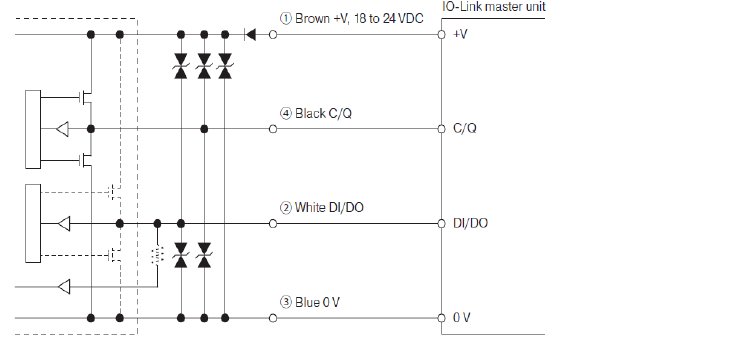
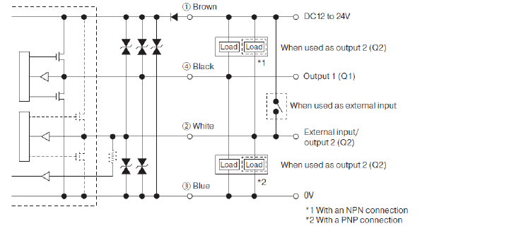
I/O circuit diagram
-
IO-Link mode
-
SIO mode (standard I/O mode) with push-pull
-
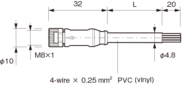
M8 connector cable
-
Connecting
■ Cut lead wires that are not used, wrap them individually with insulating tape, and do not allow them to come into contact with other terminals.
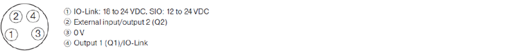
■ 1 to 4 are connector pin No.. -
Notes
■ When using a switching regulator for the power supply, be sure to ground the frame ground terminal.
■ Because wiring sensor wires with high-voltage wires or power supply wires can result in malfunctions due to noise, which can cause damage, make sure to wire separately.
■ Avoid using the transient state (Max. 2.5 s depending on the connected model) while the power is on.
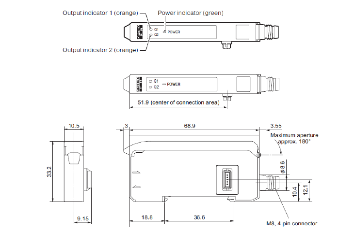
Dimensions
Unit : mm
UC2-IOL
Connector cables
M84CN-2S, M84CN-5S, M84CN-10S