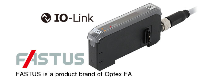
IO-Link GatewayUC2 Series
Gateway unit to connect Fiber-Optic Sensors or
displacement sensor amplifiers to IO-Link Master
- Max. 16 units of Fiber-Optic Sensors or 8 units of displacement sensor amplifier can be connected.
- Fiber-Optic Sensors or displacement sensor amplifiers can be mixed connected.
- Compact design, same size as Fiber-Optic Sensors


Lineup
| Type | Connectable Device | Model |
|---|---|---|
|
IO-Link Gateway for Sensor Amplifiers |
○ Fiber-Optic Sensors D4RF, D3RF, and D3RF Series inter-connection master and expansion unit ○ Laser Displacement Sensor CD22 Series, RS-485 communication type (connected via CDA Series) ○ Through-beam Edge Sensor TD1 Series (connected via CDA Series) |
UC2-IOL |
● For the connector type, purchase an optional connector cable.
Specifications
| Model | UC2-IOL | |
|---|---|---|
| IO-Link communication specification |
Min. cycle time | 2.2 ms |
| Baud rate | COM3 (230.4 kbps) | |
| ISDU support | Available | |
| IO-Link revision | 1.1 | |
| No. of process input data bytes | 32 bytes | |
| No. of process output data bytes | 0 byte | |
| IO-Link frame type | F-Sequence Type 2.V | |
| Connected devices | Connectable models | D4RF/D3RF/D3WF Series inter-connection main unit and expansion unit CDA Series main unit and expansion unit |
| No. of connectable units | Up to 16 *1 (One CDA unit requires two spaces.) | |
| Connection type | 5-pin connector for inter-connection (functions as an inter-connection end unit) |
|
| Indicators | Power indicator (Green), SIO: Constant, IO-Link: Blinking, Output x 2 (Orange) |
|
| Ratings | Supply voltage | SIO: 12 to 24 VDC including 10% of ripple (P-P) IO-Link: 18 to 24 VDC including 10% of ripple (P-P) (SELV and LIM or Class 2) *2 |
| Current consumption | Max. 40 mA *3 | |
| Control output | Push-Pull x 2 outputs, max. 100 mA/24 VDC (total for 2 outputs) Residual voltage: 1.8 V or less |
|
| External input | Teaching input, smart task input | |
| Connection type | Connector type: M8, 4-pin | |
| Circuit stabilization time | D4RF: 300 ms With 1 D3RF/D3WF unit inter-connected: 300 ms, with 16 D3RF/D3WF units inter-connected: 350 ms CDA+CD22: 2.5 s CDA+TD1: 350 ms |
|
| Protection circuit | Reverse connection protection, overcurrent protection | |
|
Environmental resistance |
Installation location | Indoor use |
| Operating temperature/humidity | -25 to +55°C/35 to 85% RH (no freezing or condensation) | |
| Storage temperature/humidity | -40 to +70°C/35 to 95% RH (no freezing or condensation) | |
| Vibration resistance | 10 to 55 Hz, double amplitude 1.5 mm; 2 hours in each of the X, Y, and Z directions |
|
| Shock resistance | Approx. 50 G (500 m/s2); 3 times in each of the X, Y, and Z directions | |
| Degree of protection | IP 50 (According to IEC 60529, not UL certified) | |
| Pollution degree | 2 or less | |
| Operating altitude | 2000 m or less | |
| Applicable regulation | EMC | EMC directive(2014/30/EU) |
| RoHS | RoHS directive(2011/65/EU) China RoHS (Directive 32) | |
| Applicable standards | EN 60947-5-2 | |
| Company standards | Noise resistance: Feilen Level 3 cleared | |
| Weight | Approx. 16 g | |
| Material | Housing and protective cover: PC | |
| Included accessory | Instruction manual | |
*1. The operating temperature and the load current of the control output are restricted by the number of connected units as below.
Fiber-Optic Sensors: D4RF Series
| Number of connected unit | 1 unit | 2 units | 3 to 5 units | 6 to 16 units | |
| Operating temperature | -25 to +55℃ | -25 to +55℃ | -25 to +50℃ | 25 to +45℃ | |
| Load current of control output | 1 output setting | 100 mA | 20 mA | 20 mA | 20 mA |
| 2 outputs setting | 100 mA | 10 mA | 10 mA | 10 mA | |
Fiber-Optic Sensors: D3RF/D3WF Series
| Number of connected unit | 1 to 3 unit(s) | 4 to 8 units | 9 to 16 units |
| Operating temperature | -25 to +55℃ | -25 to +50℃ | -25 to +45℃ |
| Load current of control output | 100 mA | 50 mA | 20 mA |
Displacement Sensor Amplifiers: CDA-M+CDA-S
| Number of connected unit | 1 unit (Only CDA-M) | 2 to 8 units |
| Operating temperature | -25 to +50℃ | |
| Load current of control output | Up to 100 mA per output channel | Up to 100 mA per output channel (UP to 2 A including self-consumption) |
Displacement Sensor Amplifiers: CDA-DM2+CDA-S
| Number of connected unit | 1 unit (Only CDA-DM2) | 2 to 8 units |
| Operating temperature | -25 to +50℃ | -25℃ to +45℃ |
| Load current of control output | Up to 100 mA per output channel | Up to 20 mA per output channel |
*2. Use a Class 2 power supply or a power supply that conforms to the SELV circuit (Safety Extra-Low Voltage) and the LIM circuit (Limited Energy Circuit).
*3. Not including control output load current.
● Specifications are subject to change without prior notice. Thank you for your understanding.


