Fiber-Optic SensorsD2RF/D2GF Series
Fiber-Optic Sensors featuring dual outputs, dual displays, and dual sensitivity correction functions
- Enables detection for any application
- Water resistant types (IP66) and models with analog outputs are also available
- Adapts to usage environments with its numerous functions

D2RF/D2GF Series will be discontinued by March, 2023.
(Except for analog output models)
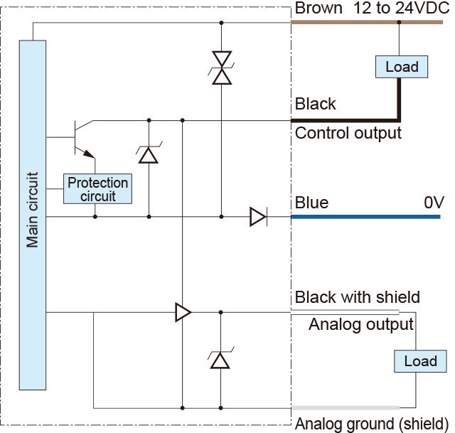
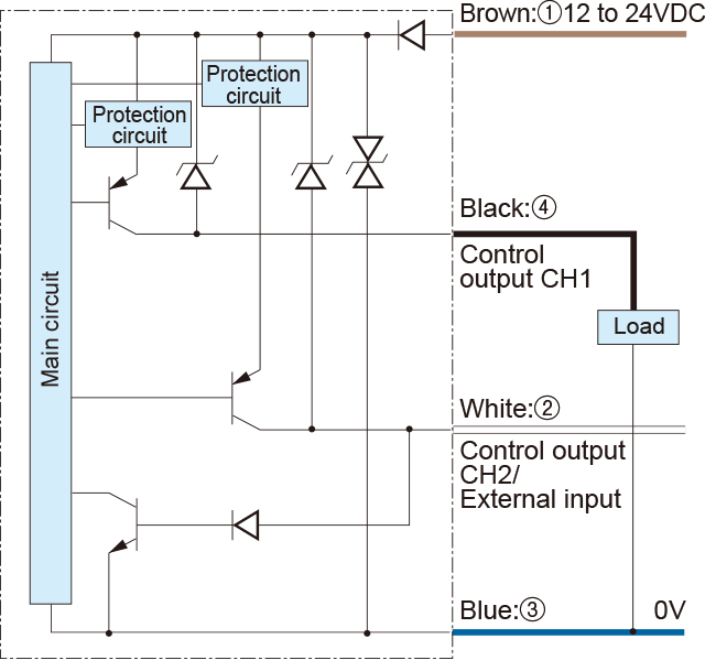
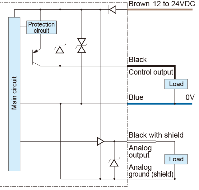
I/O circuit diagram
-
D2RF-2TN/D2RF-2TCN4, D2RF-TN/D2RF-TCN4,D2RF-TMN/D2RF-TMCN4, D2RF-TSN/D2RF-TSCN4, D2GF-TN/D2GF-TCN4, D2GF-TMN/D2GF-TMCN4, D2GF-TSN/D2GF-TSCN4
NPN output type
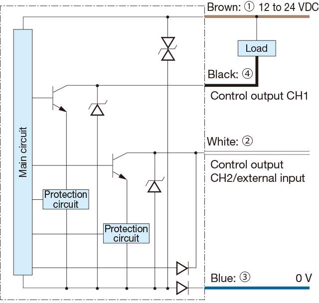
*The D2☐F-TS☐☐☐ slave unit does not have power supply wires (brown/blue) because power is supplied from the master unit.
-
D2RF-TAN, D2RF-2TAN
NPN with Analog output
-
PNP output type
-
PNP with Analog output
-
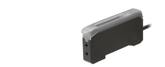
Connector type
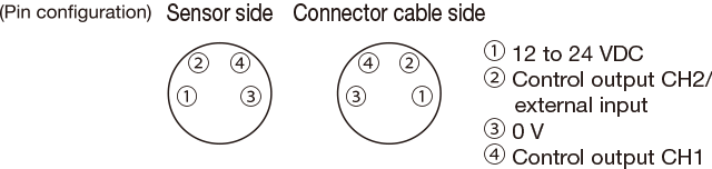
Connecting
▪When not used for control output CH2 or external input, cut the lead wire and wrap it individually with insulating tape, and do not connect it to any other terminal.
▪1 to 4 correspond to connector pin No. -
Notes
▪When using a switching regulator for the power supply, be sure to ground the frame ground terminal.
▪Because wiring sensor wires with high-voltage wires or power supply wires can result in malfunctions due to noise, which can cause damage, make sure to wire separately.
▪Avoid using the transient state while the power is on (approx. 100 ms).
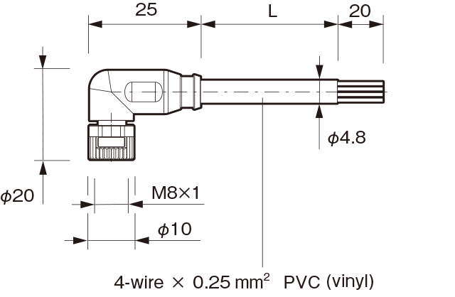
▪The connector direction is set as in the diagram below when using the L-shaped connector cable. Be aware that rotation is not possible.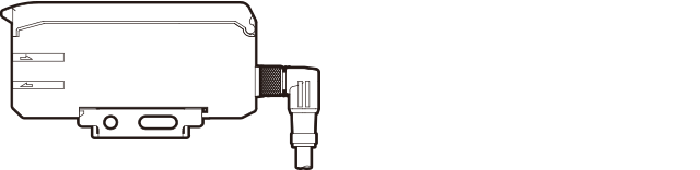
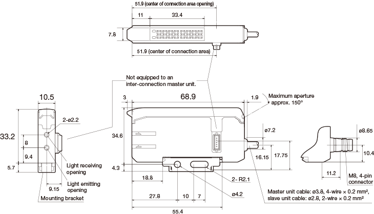
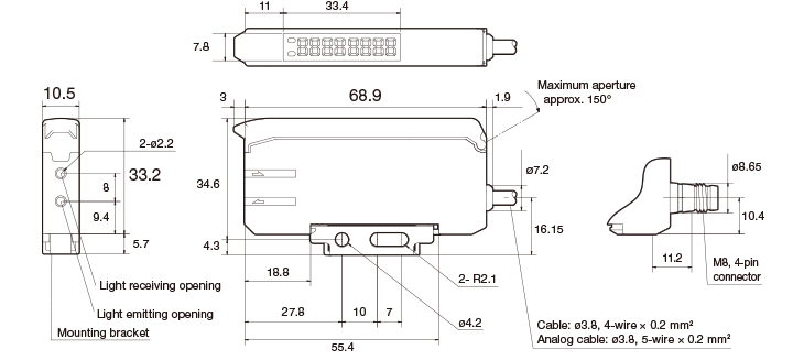
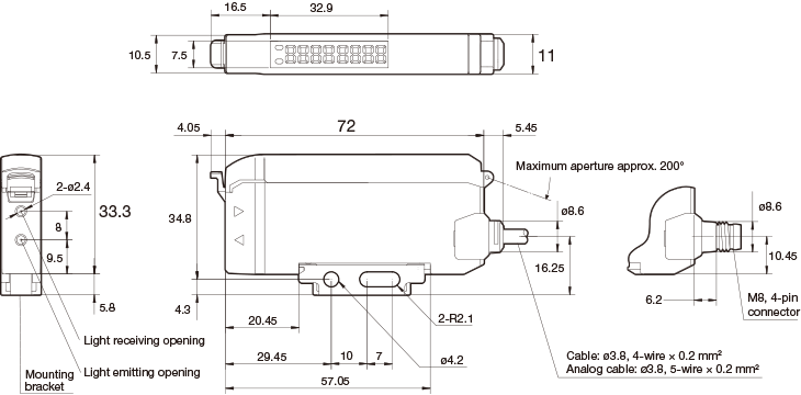
Dimensions
Inter-connection type
D2RF-TMN(P), D2RF-TMCN(P)4
D2RF-TSN(P), D2RF-TSCN(P)4
D2GF-TMN(P), D2GF-TMCN(P)4
D2GF-TSN(P), D2GF-TSCN(P)4
Stand-alone type
D2RF-TN(P), D2RF-TCN(P)4, D2RF-TAN(P)
D2GF-TN(P), D2GF-TCN(P)4
Water resistant stand-alone type
D2RF-2TN, D2RF-2TCN4, D2RF-2TAN
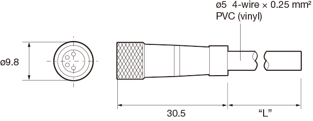
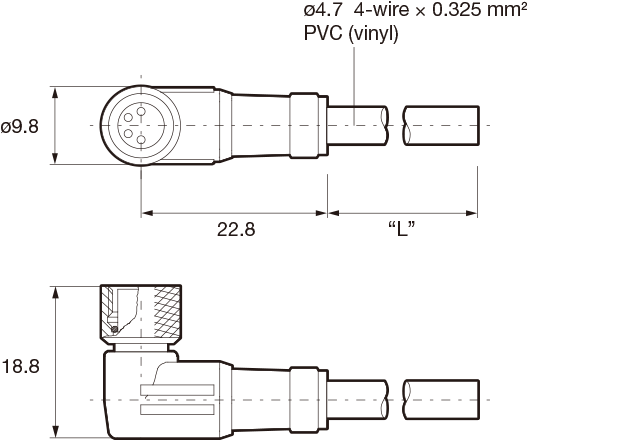
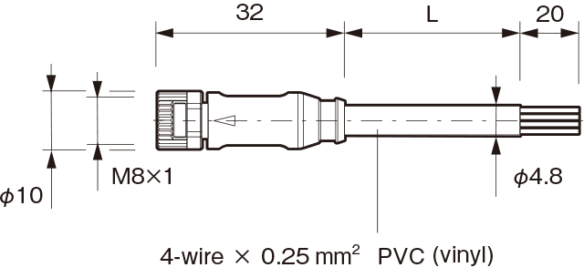
Connector cable (optional)
-
JCN-S, JCN-5S, JCN-10S
-
JCN-L, JCN-5L, JCN-10L
Successor models
M84CN-2S, M84CN-5S, M84CN-10S
M84CN-2L, M84CN-5L, M84CN-10L