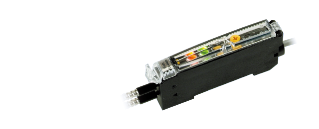
Potentiometer Fiber-Optic SensorsBRF/BGF Series
Easy sensitivity adjustments without the use of tools
- Easy to turn sensitivity adjustment potentiometer
- High-speed response up to 50μs
 BGF Series was discontinued in May, 2024.
BGF-T Series will be discontinued by March, 2025.
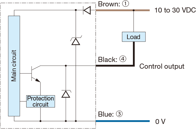
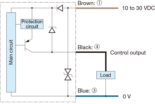
Output circuit diagram
-
NPN output type
-
PNP output type
-
Connector type
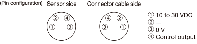
-
Connecting
▪1to 4 are connector pin No.
Notes
▪When using a switching regulator for the power supply, be sure to ground the frame ground terminal.
▪Because wiring sensor wires with high-voltage wires or power supply wires can result in malfunctions due to noise, which can cause damage, make sure to wire separately.
▪Avoid using the transient state while the power is on (approx. 100 ms).
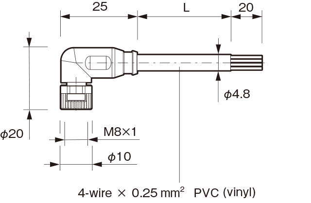
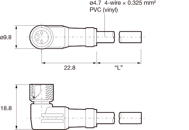
▪The connector direction is fixed as the drawing below when you use L-shaped connector cable. Be aware that rotation is not possible.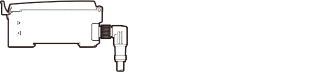
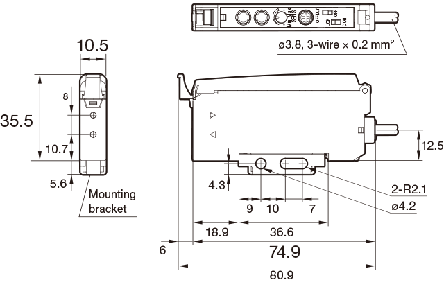
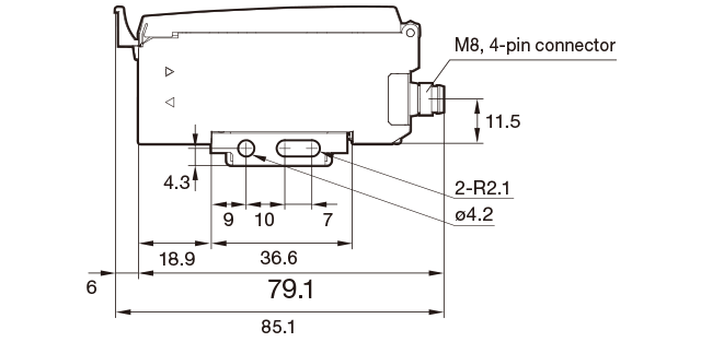
Dimensions
Unit : mm
Fiber-Optic Sensors
-
Cable type
-
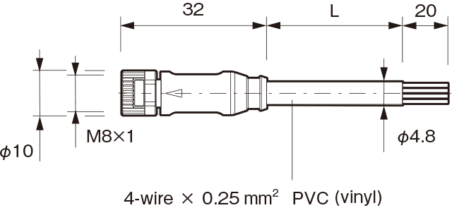
Connector type
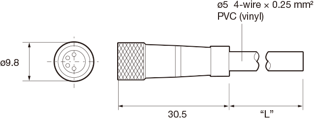
Connector cable (optional)
-
JCN-S, JCN-5S, JCN-10S
-
JCN-L, JCN-5L, JCN-10L
Successor models
M84CN-2S, M84CN-5S, M84CN-10S
M84CN-2L, M84CN-5L, M84CN-10L