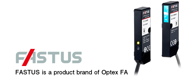
Through-beam Edge Laser SensorsTD1 Series
Edge Position Measurement for Any Workpiece
- Suitable for edge measurement and width/gap measurement
- Light axis alignment function for easy installation
- Easily readable amplifier unit
Sold separately: CDA-DM2

amplifier unit (Options)
-
- Displacement sensor amplifier unit
- CDA Series
- CDA-DM2
Features an organic EL display that can display clearly in both Japanese and English.
Calculations can be performed with up to two TD1 series units. -

-
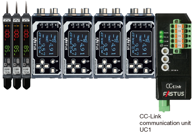
Connect with CC-Link to achieve “sensor visibility”
By connecting a CDA series to a communication unit, connection to a CC-Link network is possible.
It supports Mitsubishi iQ Sensor Solution (iQSS) and batch management of sensors can be performed easily with GX Works2.
-

-
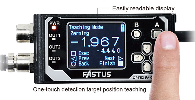
Simple Teaching Mode
When teaching, the edge center position can be set as desired within the measurement range. Simply place the measurement target and press the button.
-
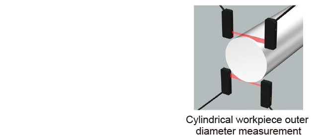
Calculation Function
Connecting two TD1 series units enables measurement of workpieces with outer diameters of 10 mm or more..
-

Specifications
| Type | 1 × analog output 2 × external inputs 3 × control outputs |
2 × high-resolution analog outputs 1 × external input 2 × control outputs |
||
|---|---|---|---|---|
| Main unit | Expansion unit | Main unit | ||
| Model | CDA-M | CDA-S | CDA-DM2 | |
| Sensor head (TD1 Series) |
Number of connectable sensors | Max. 2 sensors per CDA unit | ||
| Connection type | Amplifier side: M8, 4-pin connector | |||
| Communication I/F | RS-485 compliant (Overall cable length: Within 10m) | |||
| Rating | Supply voltage | 12 to 24 VDC ±10%, including 10% ripple (p-p) | Supplied from the main unit or UC1/UC2 *1 | 12 to 24 VDC ±10%, including 10% ripple (p-p) |
| Current consumption | 100 mA or less (at 12 V) |
100 mA or less (at 12 V) |
120 mA or less (at 12 V) |
|
| Display | Dot matrix display | OLED 128 x 96 pixels | ||
| Indicators | Power indicator (PWR): red/green, output indicators (OUT1/OUT2/OUT3): orange |
|||
| Analog output | No. of outputs | 1 | 1 | 2 |
| Type | 4 to 20 mA: Load impedance; 300 Ω or less |
4 to 20 mA: Load impedance; 300 Ω or less |
4 to 20 mA: Load impedance; 300 Ω or less 0 to 10 V: Output impedance; 100 Ω (selectable by setting) |
|
| Control output | No. of outputs | 3 | 3 | 2 |
| Type | NPN/PNP open collector (selectable by setting) Max. 100 mA/30 VDC, Residual voltage: 1.8 V or less |
|||
| External input | 2 inputs | 2 inputs | 1 input | |
|
Environmental resistance |
Ambient temperature/humidity | -20 to +50℃ / 35 to 85% RH (no freezing or condensation) | ||
| Storage temperature/humidity | -20 to +60℃ / 35 to 85% RH (no freezing or condensation) | |||
| Vibration resistance | 10 to 55 Hz; double amplitude 1.5 mm; 2 hours in each of the X, Y, and Z directions |
|||
| Shock resistance | Approx. 50 G (500 m/s2), 3 times in each of the X, Y, and Z directions |
|||
| Protection circuit | Reverse connection protection, overcurrent protection | |||
| Degree of protection | IP50 (IEC 60529) | |||
| Applicable regulations |
EMC | EMC directive (2014/108/EU) | ||
| Environment | RoHS directive (2011/65/EU), China RoHS (Directive No. 32) | |||
| Applicable standards | EN 60947-5-7 | |||
| NRTL Certification | UL Recognized Components | |||
| Material | Polycarbonate | |||
| Weight (including cable) | Approx. 170 g | |||
*1: Supply 12 to 24 VDC to the power wires (brown and blue) of the cable as the supply voltage for the compatible sensors.
• CDA-DM models have been discontinued. Please use the CDA-DM2 successor model. Click here for more information.


