


Small Laser Displacement SensorsCD33 Series
Half-palm size. Ideal for built-in use with smaller machines.
- Specular reflection types have been added to the line up
- Control units for Mitsubishi Electric PLC are available


I/O circuit diagram
-
Analog output type (NPN output type)
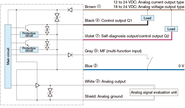
-
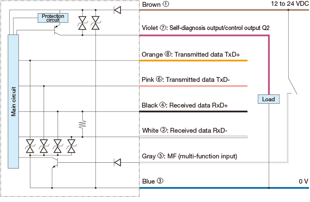
RS-422 type (NPN output type)
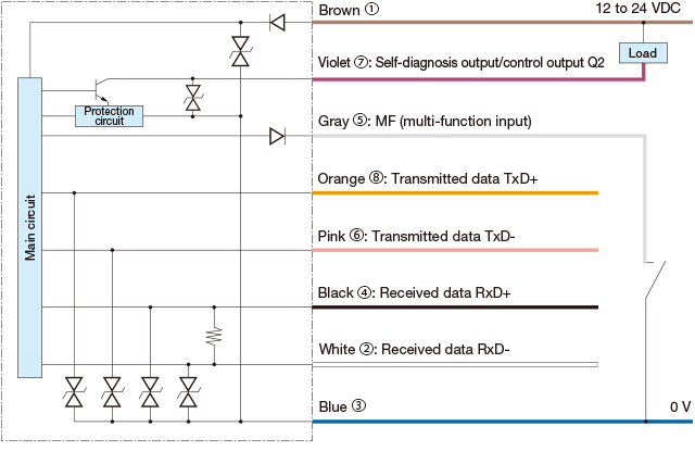
-
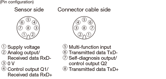
Connector type
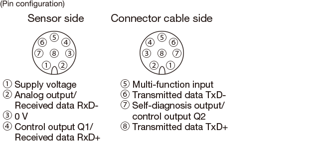
-
Connecting
▪ 1 to 8 are connector pin No.
▪ Because the connector type is not equipped with an analog ground wire, please use by connecting the analog ground terminal of the analog input device and 0 V of the sensor power supply.Notes
▪ When using a switching regulator for the power supply, be sure to ground the frame ground terminal.
▪ Avoid wiring in parallel with or in the same piping as high-voltage wires or power lines. Doing so may lead to malfunctions caused by noise. Also, shorten the power supply and signal wires as much as possible.
▪ Avoid using the transient state while the power is on (approx. 1.5 s).
-
Analog output type (PNP output type)
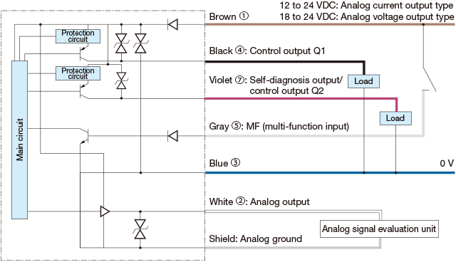
-
RS-422 type (PNP output type)
-
Connector type
-
Connecting
▪ 1 to 8 are connector pin No.
▪ Because the connector type is not equipped with an analog ground wire, please use by connecting the analog ground terminal of the analog input device and 0 V of the sensor power supply.Notes
▪ When using a switching regulator for the power supply, be sure to ground the frame ground terminal.
▪ Avoid wiring in parallel with or in the same piping as high-voltage wires or power lines. Doing so may lead to malfunctions caused by noise. Also, shorten the power supply and signal wires as much as possible.
▪ Avoid using the transient state while the power is on (approx. 1.5 s).
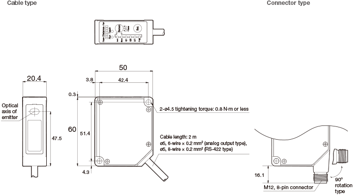
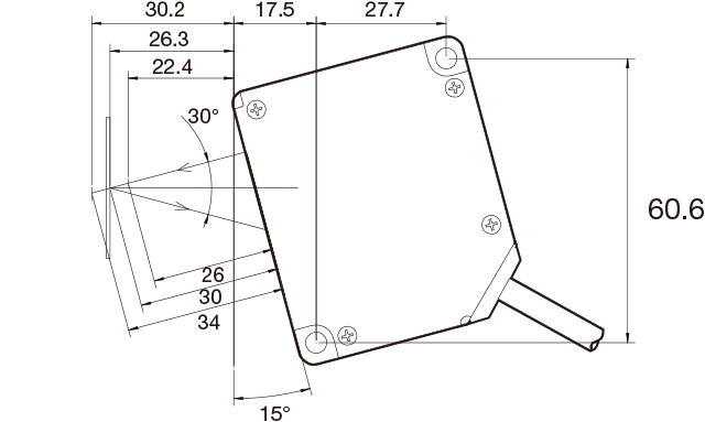
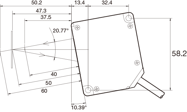
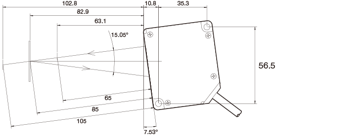
Dimensions
Sensor
Specular reflection type (side view)
-
CD33-L30☐-422
-
CD33-L50☐-422
CD33-L85☐-422
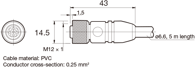
Connector cable
-
DOL-1208-G05MF
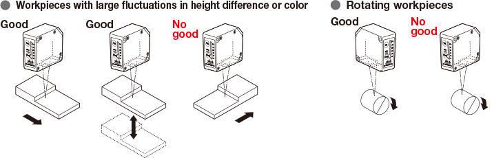
Installation of sensor

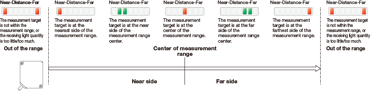
Mount the sensor head so that the detection surface (optical plane) is always parallel to the detection target. Adjust the target so that the spot aligns with the detection position, and ensure that the bar graph distance indicator lights up orange at the reference detection surface (center of change).
Bar graph distance indicator
By combining individual lighting/multiple lighting and lighting/flashing patterns, distances will be displayed in 25 steps (the following example shows 5 steps).

Precautions for laser use
-
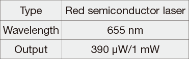
This product emits a Class 1/Class 2 (II) visible laser beam that is compliant with JIS C 6802/IEC/FDA laser safety standards.
Because English language warnings indicating the sensor as Class 1 or Class 2 (II), as well as explanation labels, are located on the side of the sensor, please replace these warnings/explanation labels with the Japanese language warnings/explanation labels included in the box when using in Japan. -

-
Type of laser used in this product
-
If you install this product in a piece of machinery that will then be exported to the United States, it is necessary to follow laser standards as stipulated by the American Food and Drug Administration (FDA).
This product has already been submitted to the CDRH (Center for Devices and Radiological Health). (Please inquire for details.)