Laser Sensors with DisplayDR-Q Series
Easy to set up, finely adjustable laser
- Sensing distance: Max. 4 m
- Digital adjustment function
- Built-in ASC (Automatic Sensitivity Correction) function

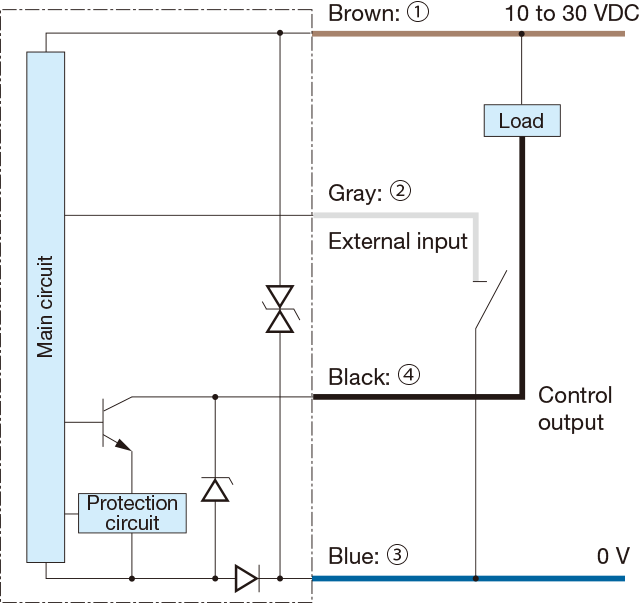
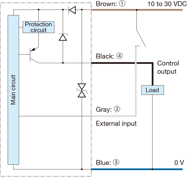
I/O circuit diagram
-
NPN output type
-
PNP output type
-
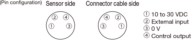
Connector type
-
Connecting
▪ When not used for external input, cut the lead wire and wrap it individually with insulating tape, and do not connect it to any other terminal.
▪ 1 to 4 are connector pin No.Notes
▪ When using a switching regulator for the power supply, be sure to ground the frame ground terminal.
▪ Because wiring sensor wires with high-voltage wires or power supply wires can result in malfunctions due to noise, which can cause damage, make sure to wire separately.
▪ Avoid using the transient state while the power is on (approx. 100 ms).
▪ The connector direction is fixed as in the drawing below when you use L-shaped connector cable. Be aware that rotation is not possible.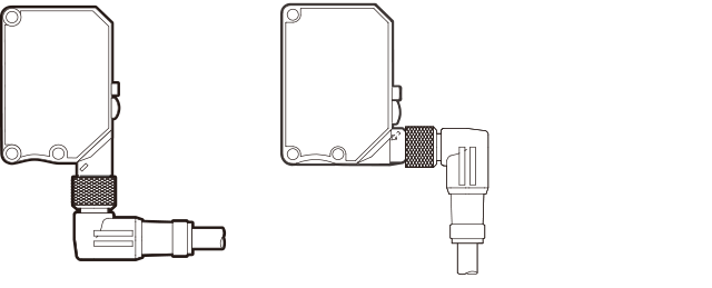
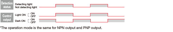
Operation mode
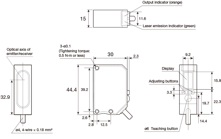
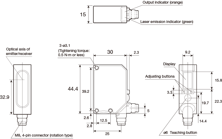
Dimensions
Sensor
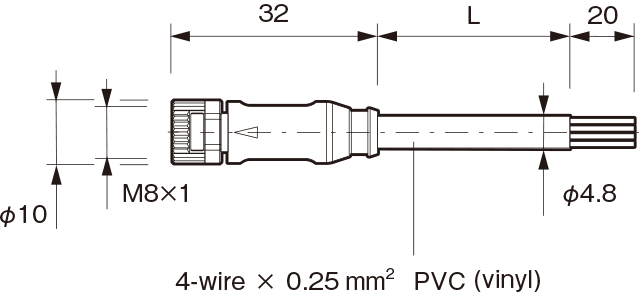
Cable type
Connector type
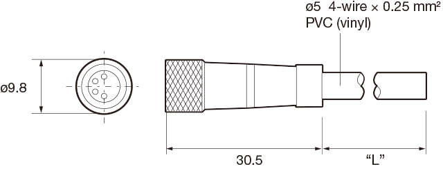
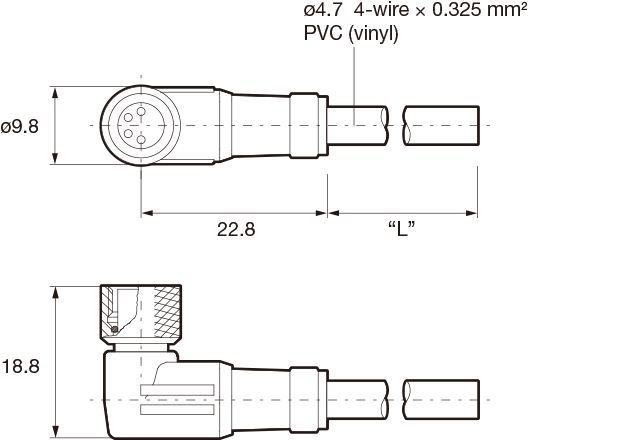
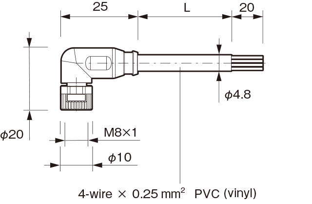
Connector cable (optional)
-
JCN-S, JCN-5S, JCN-10S
-
JCN-L, JCN-5L,JCN-10L
Successor models
M84CN-2S, M84CN-5S, M84CN-10S
M84CN-2L, M84CN-5L, M84CN-10L
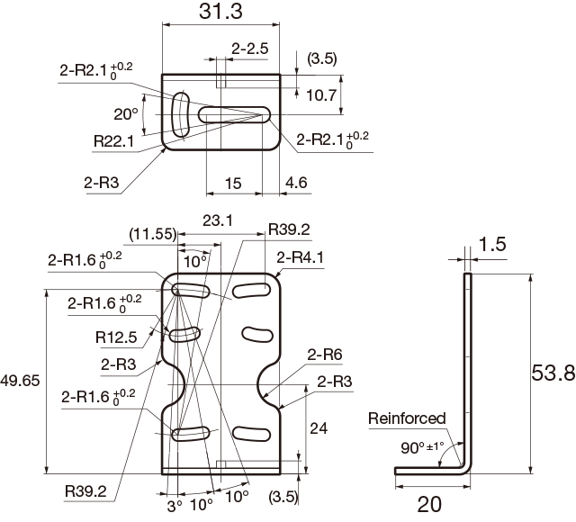
Mounting bracket
-
BEF-WK-190 (included)
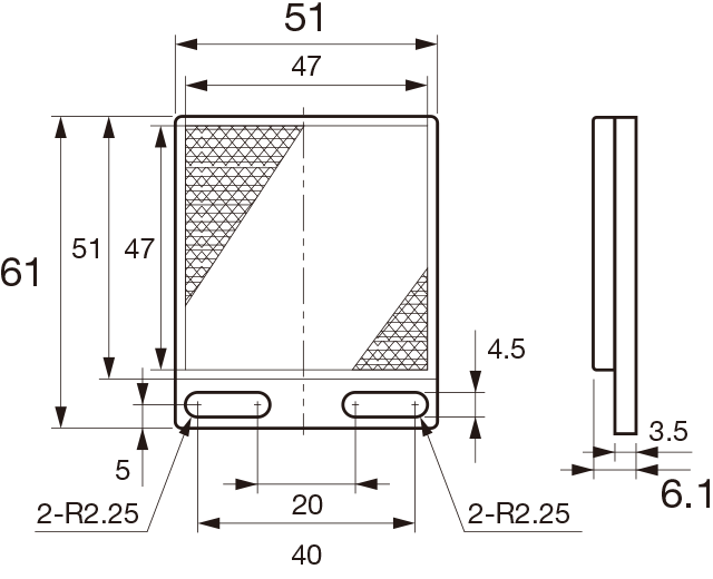
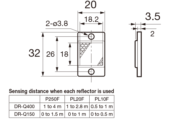
Reflector
-
P250F (included)
-
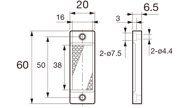
PL20F (optional)
-
PL10F (optional)
Notes for sensor usage
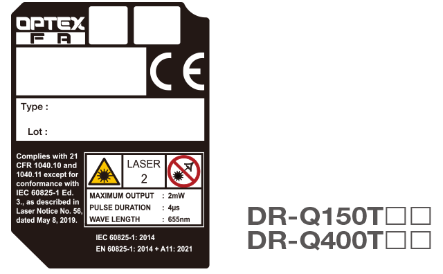
-
This product emits a Class 2 (II) visible laser beam that is compliant with JIS C 6802/IEC 60825- 1/FDA laser safety standards.
Warning and explanation labels are affixed to the sides of the sensor.
-