


Fiber-Optic SensorsD12R Series
Easy-to-Use, Simple Fiber-Optic Sensors
- Easy-to-read OLED display
- Cross-talk prevention
- Extensive external input capabilities


I/O Circuit Diagrams
-
NPN setting

-
PNP or Push-pull setting

-
M8 connector pin

-
Connecting
■ ① to ④ are connector pin No.
■ Lead wires that are not in use should be wrapped individually with insulating tape, and do not connect it to any other terminal. -
Notes
■ When using a switching regulator for the power supply, be sure to ground the frame ground terminal.
■ Because wiring sensor wires with high-voltage wires or power supply wires can result in malfunctions due to noise, which can cause damage, make sure to wire separately.
■ Avoid using the transient state while the power is on (approx. 300 ms).
■ The connector direction is fixed as the drawing below when you use L-shaped connector cable.
Be aware that rotation is not possible.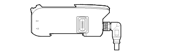
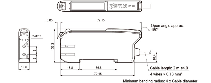
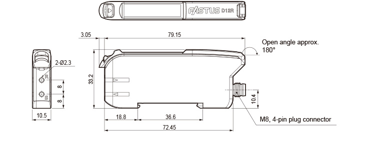
Dimensions
Cable type
Connector type
Mounting bracket
BEF-001 (optional)

End plate
BEF-002 (optional)

Connector cables (optional)
M84CN-2S, M84CN-5S, M84CN-10S
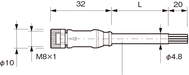
L = 2,000 (M84CN-2S)
L = 5,000 (M84CN-5S)
L = 10,000 (M84CN-10S)
Cable material: PVC
Conductor cross-section:
4-wire x 0.25 mm2
Minimum bending radius:
24 mm (when fixed in place)M84CN-2L, M84CN-5L, M84CN-10L
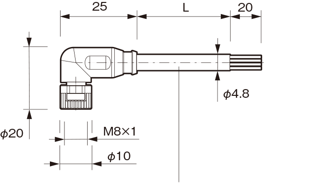
L = 2,000 (M84CN-2L)
L = 5,000 (M84CN-5L)
L = 10,000 (M84CN-10L)
Cable material: PVC
Conductor cross-section:
4-wire x 0.25 mm2
Minimum bending radius:
24 mm (when fixed in place)