


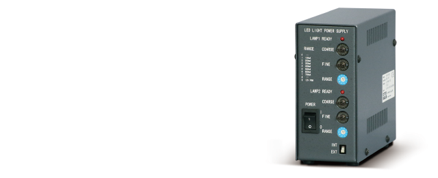
Dual-Output Power Supply (CC+PWM)OPPCW Series
Dual output with 12 V PWM and constant current
- Digital dimming method (256 steps using front switch)
- Support for 8-bit parallel and 0 to 5 V analog input for external dimming control
Circuit diagram
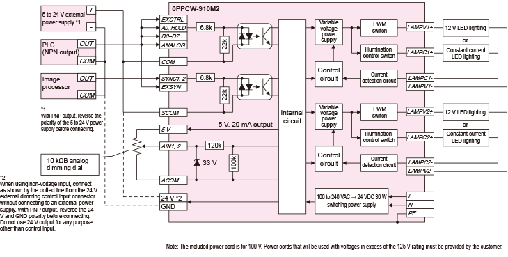
Illumination Output
12 V PWM
| Pin No. | Signal Name |
|---|---|
| 1 | + |
| 2 | - |
*Extension cable model: OP-CB1-☐ (cable length)
CONSTANT CURRENT
| Pin No. | Signal Name |
|---|---|
| 1 | NC |
| 2 | - |
| 3 | + |
*Extension cable model: OP-CBCH1-☐ (cable length)
External Lighting Control Input
EXT ON/OFF external lighting connector
| Pin No. | Terminal Marking | Function |
|---|---|---|
| 1 | SYNC1 | LAMP1 ON |
| 2 | SYNC2 | LAMP2 ON |
| 3 | EXSYN | External control switching COM |
| 4 | SCOM |
*External lighting control cable: OP-ECB2-☐ (cable length)
External Dimming Control Input
EXT CTRL external dimming control input connector
| Pin No. | Terminal Marking | Function |
|---|---|---|
| 1 | COM | Digital input common |
| 2 | EXCTRL | Digital input switching |
| 3 | A0 | OFF: LAMP1, ON: LAMP2 |
| 4 | HOLD | Not configurable when ON |
| 5 | D7 | Bit 7 (MSB) |
| 6 | D6 | Bit 6 |
| 7 | D5 | Bit 5 |
| 8 | D4 | Bit 4 |
| 9 | D3 | Bit 3 |
| 10 | D2 | Bit 2 |
| 11 | D1 | Bit 1 |
| 12 | D0 | Bit 0 (LSB) |
| 13 | ANALOG |
Analog input switching (for use between 1 COM) |
| 14 | GND | Ground |
| 15 | 24 V | 24 V output |
| 16 | 24 V | 24 V output |
| 17 | AIN1 |
LAMP1 0 to 5 V analog input |
| 18 | AIN2 |
LAMP2 0 to 5 V analog input |
| 19 | 5 V | 5 V output |
| 20 | ACOM | AIN1/2 common |
*External dimming control cable: OP-ECBM20-3