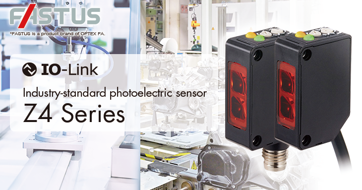
Features
■ IO-Link connection supported
● Easy integration in application with Fieldbus/IO-Link network
● Monitoring of light receiving level for sensing status and maintenance time prediction
● Parameter setting of sensitivity, ON/OFF mode and timer via network
■ Enhanced ambient illuminance resistance against sunlight, incandescent and LED lights
■ Brighter status indicators for remote status monitoring
Lineup
| Optical system | Sensing range | Model | ||
|---|---|---|---|---|
| NPN type | PNP type | |||
| Through-beam |  |
 |
Z4T-2500N
Z4T-2500CN4 |
Z4T-2500P
Z4T-2500CP4 |
| Retro reflective |  |
 |
Z4R-400N
Z4R-400CN4 |
Z4R-400P
Z4R-400CP4 |
| Diffuse reflective |  |
 |
Z4D-100N Z4D-100CN4 |
Z4D-100P (Z4D-100CP4 |
| Limited diffuse reflective |
 |
 |
Z4D-L09N
Z4D-L09CN4 |
Z4D-L09P
Z4D-L09CP4 |
Specifications
| Through-beam | Retro reflective | Diffuse reflective | Limited diffuse reflective | |||
|---|---|---|---|---|---|---|
| Model | NPN | Cable type | Z4T-2500N | Z4R-400N | Z4D-100N | Z4D-L09N |
| M8 connector type | Z4T-2500CN4 | Z4R-400CN4 | Z4D-100CN4 | Z4D-L09CN4 | ||
| PNP | Cable type | Z4T-2500P | Z4R-400P | Z4D-100P | Z4D-L09P | |
| M8 connector type | Z4T-2500CP4 | Z4R-400CP4 | Z4D-100CP4 | Z4D-L09CP4 | ||
| Sensing distance | 25 m | 0.01 to 4 m*1 | 0 to 1 m*2 | 10 to 90 mm*3 | ||
| Light source | 4-element red LED, Wavelength: 632 nm | |||||
| Spot size | Approx. ø1800 mm (At distance of 25 m) |
Approx. ø280 mm (At distance of 4 m) |
Approx. ø75 mm (At distance of 1 m) |
Approx. ø8 mm (At distance of 90 mm) |
||
| Response time | 500 μs or less | |||||
| Hysteresis | - | - | 20 % Max. | 10 % Max. | ||
| Sensitivity adjustment | 1-turn potentiometer or via IO-Link network | |||||
| Indicators | Output indicator: Orange, Stability indicator: Green (No indicators equipped on through-beam type emitter) |
|||||
| Control output | NPN/PNP Open collector, Max. 100 mA / 30 VDC, Residual voltage 1.8 V Max. |
|||||
| Output mode | Light ON / Dark ON by selection switch or via IO-Link network | |||||
| IO-Link specification | Ver. 1.1, Transmission rate: COM 3 (230.4 kbps), Process data length: 4 byte, Min. cycle time: 1.0 ms |
|||||
| Timer function | ON delay / OFF delay /One-shot only via IO-Link network | |||||
| Cable connection | Cable: 2m, ø3.8 mm / Connector: M8 4-pin | |||||
| Protection circuit | Reverse connection protection, Overcurrent protection | |||||
| Rating | Supply voltage | 10 to 30 VDC, including 10% ripple (p-p) | ||||
| Current consumption*4 |
Emitter: 14 mA or less Receiver: 20 mA or less |
20 mA or less | 20 mA or less | 20 mA or less | ||
| Applicable regulations |
EMC | EMC directive (2014/30/EU) | ||||
| RoHS | RoHS directive (2011/65/EU), China RoHS (Directive 32) | |||||
| Applicable standards | EN 60947-5-2 | |||||
| NRTL Certification | UL Recognized Component (Under development) | |||||
| Environmental resistance |
Ambient temperature | –25 to +55°C (No freezing) | ||||
| Ambient humidity | 35 to 85% RH (No condensation) | |||||
| Ambient illuminance | Sunlight: 50.000 lx or less, Incandescent lamp: 5,000 lx or less | |||||
| Vibration resistance | 10 to 55 Hz, double amplitude 1.5 mm, 2 hours in each of the XY and Z directions |
|||||
| Shock resistance | 1000 m/s2 (Approx. 100 G), 3 times in each of the XY and Z directions | |||||
| Protection category | IP67 | |||||
| Material | Housing: ABS, Front cover: PMMA | |||||
| Weight without cable | Approx. 10 g | |||||
| Included accessories | Instruction manual | |||||
*1. With the V-61 reflector.
*2. Using a 200 x 200 mm white sheet paper.
*3. Using a 100 x 100 mm white sheet paper.
*4. Not including control output load current.
Accessories
-
Reflectors
Model Feature V-61 Standard, 60.9 × 50.9 mm, 0.01 to 4 m V-42 Small, 42 × 35 mm, 0.01 to 2.4 m P45A Vertical, 54 × 12.4 mm, 0.01 to 1.4 m P25 Side mount, 32 × 14 mm, 0.01 to 1.6 m V-30 Ultra-small, 43 × 23 mm, 0.01 to 2.2 m M8 connector cables
Model Feature M84CN-2S Straight, 2 m M84CN-5S Straight, 5 m M84CN-10S Straight, 10 m M84CN-2L L-shaped, 2 m M84CN-5L L-shaped, 5 m M84CN-10L L-shaped, 10 m -
Mounting brackets
Model Feature BEF-W100-B For cable type, Floor mounted BEF-W100-A For connector type, Back-mounted Protective mountig brackets
Model Feature LK-S01 Floor mounted LK-S02 Wall mounted Slit masks (For Through-beam)
Model Feature BL-W100 Width: 0.5 mm, 1 mm, 2 mm,
2 sheetsBL-100-M1-10pcs Width: 1 mm, Stainless steel,
10 piecesBL-100-M05 Width: 0.5 mm, Stainless steel,
2 piecesAnti-interference filter (For Through-beam)
Model Feature BL-100-POLF POL filter, vertical and horizontal, 2 sets of each
● Mounting bracket is not included. Purchase as necessary.
● Reflector is not included with the retro-reflective type. Purchase an optional reflector.
● For the connector type, purchase an optional connector cable.
● For IO-Link connection with USB adapter and master unit, use 3rd party product in the market.
Circuit diagram
-
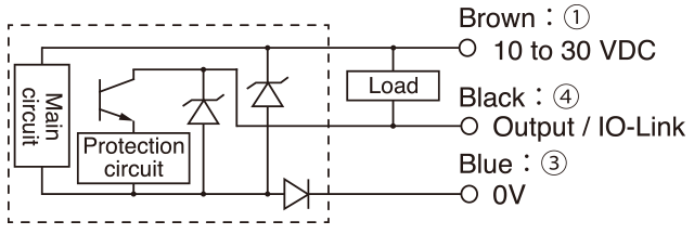
[NPN output]
-
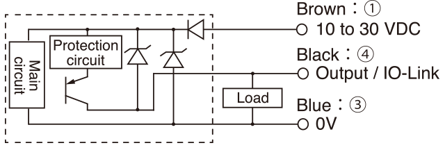
[PNP output]
-
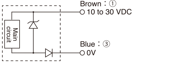
[Emitter for through-beam]
-
[M8 connector pin layout]

Dimensions
(Unit : mm)
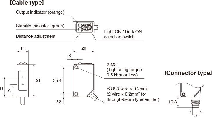
-
Type A:Emitter optical axis B:Receiver optical axis Through-beam - 19(Emitter & Receiver) Retro-reflective 11.9 19 Diffuse-reflective Limited diffuse reflective 18.8 Never use these products as sensing devices for personnel protection.
Doing so could lead to serious injury or death.
Before use please read an instruction manual.
● Specifications are subject to change without prior notice.


