

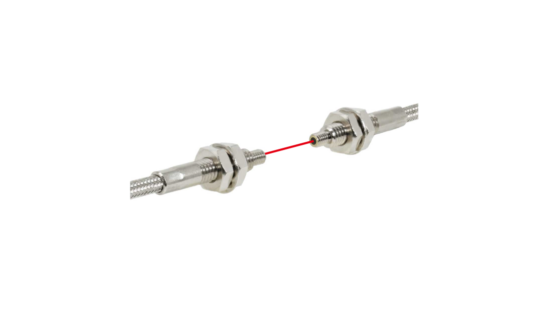
Specifications
| Part No. | 51689 |
|---|---|
| Model | NF-TH12 |
| Category | Heat resistant type |
| Type |
M4 Joint type Lens attachable |
| Detection method | Through-beam type |
| Optical axis direction | Straight view |
| Shape of fiber head |
M4 23 mm long |
| Sleeve | - |
| Optical axis diameter | ø1.0 mm |
| Fiber length |
Heat/Cold resistant side 0.2 m Ambient temperature fiber side 2 m |
| Free-cut | Possible only in the ambient temperature fiber |
| Min. bending radius |
Heat/Cold resistant side R18 Ambient temperature fiber side R25 |
| Degree of protection | - |
| Ambient temperature |
-60 ... +200°C 0 ... 40°C (at 85 % RH) |
| Ambient humidity | 35 ... 85 % RH |
| Applicable regulations | RoHS directive (2011/65/EU) |
| Weight | Approx. 45 g |
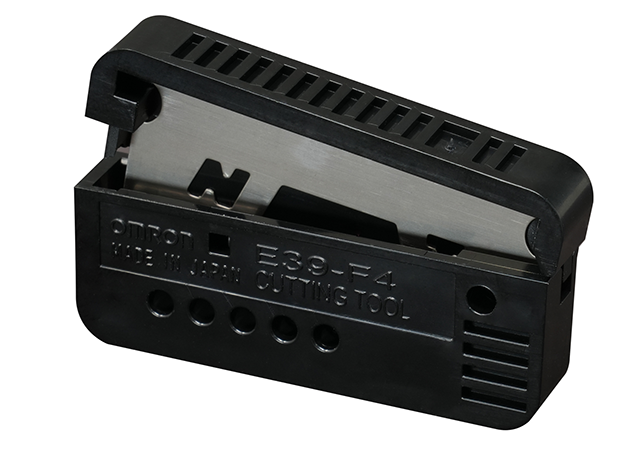
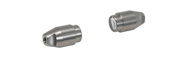
| Included items | Fiber cutter, M4 Hex nut x 6, Toothed washer x 2, M4 Hex nut (Plastic) x 2, Spring washer x 2 |
● The optical axis diameter is an approximate value.
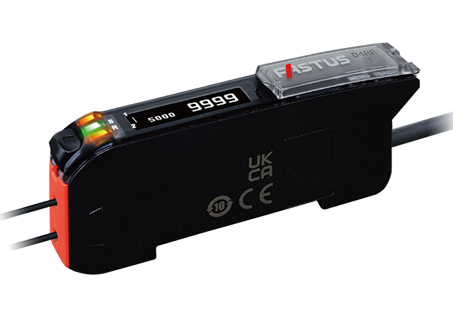
Sensing Distance by Response Time
Unit: mm
| Fiber-Optic Sensor D4RF Series | Fiber-Optic Sensor D12R Series | ||
|---|---|---|---|
|
2,990 (8 ms) 2,065 (2 ms) 1,570 (1 ms) 1,330 (500 μs) 1,080 (250 μs) 680 (70 μs) 230 (16 μs/22 μs) |

|
2,500 (4 ms) 1,345 (1 ms) 950 (250 μs) 235 (50 μs) |
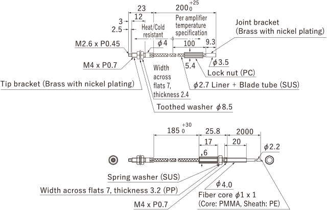
Dimensions
Unit: mm
Mounting Method
-
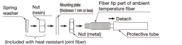
Connecting heat resistant joint fiber to ambient temperature fiber
- Use the following procedure to connect ambient temperature fiber.
Procedure
-
Attach the plastic nut included with the heat resistant joint fiber and spring washer as far as possible on the fiber tip of the ambient temperature fiber.

-
Mount the heat resistant joint fiber and ambient temperature fiber using a lock nut.

Note 1: Do not secure the lock nut using the plastic nut and spring washer from Procedure 1.
-
To prevent the lock nut from becoming loose, secure using the plastic nut used for mounting in Procedure 1.

-
If mounting connecting parts to the mounting plate
- If securing parts that connect the heat resistant joint fiber and ambient temperature fiber to the mounting plate using the included metal nuts, use the procedure below.
- The mounting plate thickness needs to be 1 mm or less.
Procedure
- Remove the protective tube from the ambient temperature fiber, attach the included metal nut from the tip of the fiber and move it to the fiber part.
- Insert the tip of the fiber into the mounting plate.
- Connect the heat resistant joint fiber to the ambient temperature fiber using the same procedure from <Connecting heat resistant joint fiber to ambient temperature fiber>
-
Tighten the metal nut mounted in Procedure 1 to the mounting plate.
<Operating Temperature>
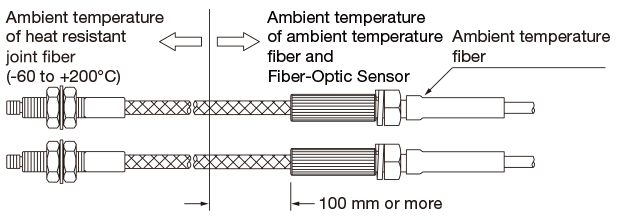
- In order to protect ambient temperature fiber and Fiber-Optic Sensor, keep the heat resistant joint fiber at least 100 mm from the boundary of the ambient temperature as shown in the diagram below.
Usage notes
-
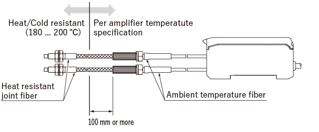
- In order to protect Fiber-Optic Sensor, keep the heat resistant fiber part at least 100 mm from the boundary of the ambient temperature as shown in the diagram below.
- Do not directly expose Fiber-Optic Sensor to radiation heat or hot air.
- The tip bracket of the heat resistant fiber (up to 350°C) and stainless steel sheath may change color when used at high temperatures, but this does not affect their detection capability.
Accessories

Correct Use
Contact Us
Our experts quickly deliver the best plan for your needs and provide continuous support throughout the process.
Product Inquiry / Technical Support- Download List
- 20