


IO-Link Master
UR Series
Highly functional IO-Link Master for various industrial Ethernet


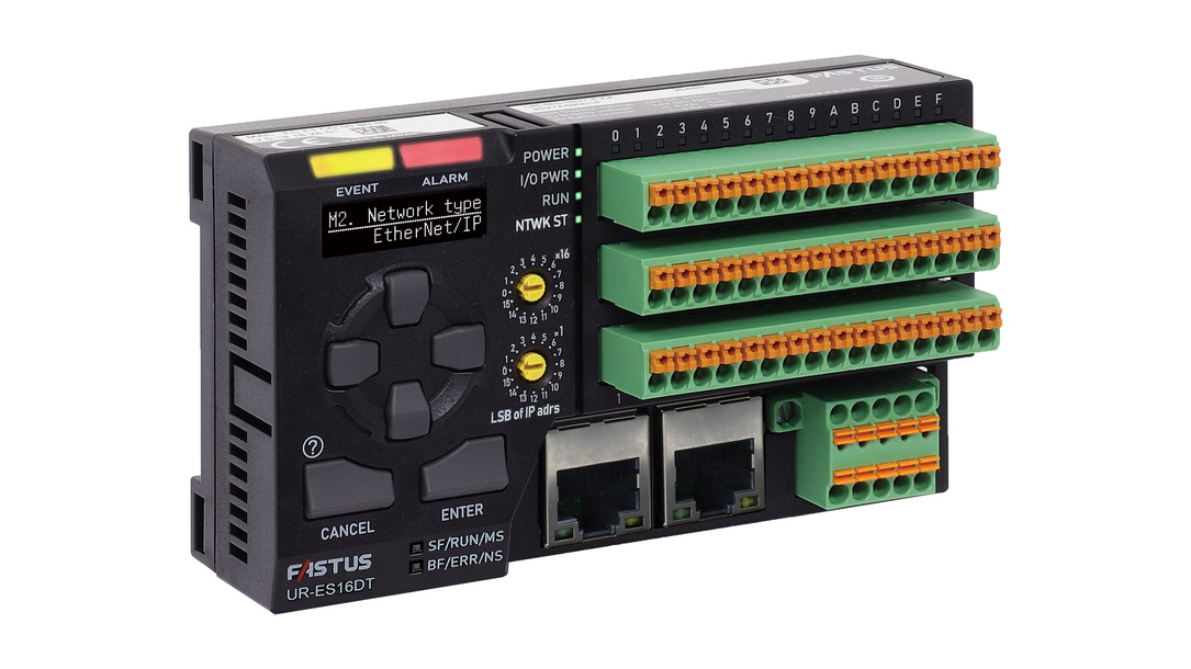







- First in industry* Mixed connection of digital Sink(NPN) / Source(PNP) I/O devices is realized with one unit
- Largest no. in industry* 16 channels
- Fastest in industry* Realized the minimum cycle time of 0.3 ms
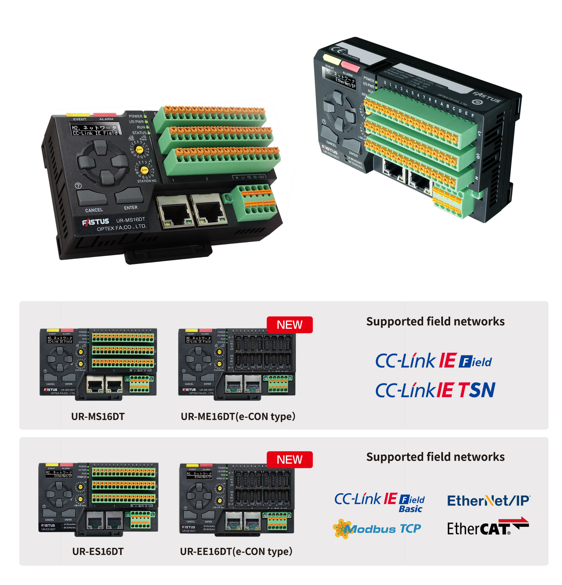
- NEW MODELSe-CON type, UR-ME/EE16DT added to lineup
IO-Link Master UR Series
First in industry FPGA-based IO-Link communication processing and unique design enable first in industry functions and performance.
The interface and compact body design give form to the true needs of the field.
The new standard IO-Link Master is now available.
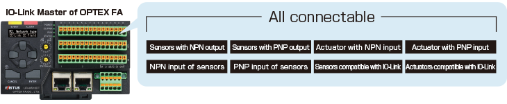
A single unit to connect digital Sink(NPN) and Source(PNP) I/O devices
A single unit to connect digital Sink(NPN) and Source(PNP) I/O devices.
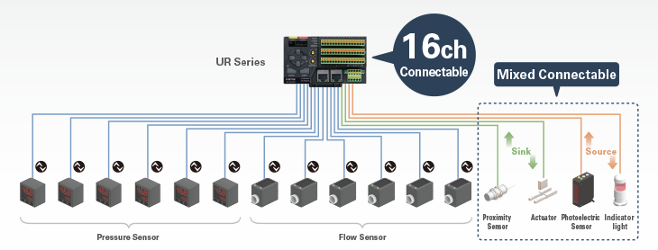
Not only IO-Link devices, but also digital Sink(NPN) / Source(PNP) I/O devices can be connected together in one unit.
16 channels
Connects to more than twice as many I/O devices as standard IO-Link Master.
Save costs and space.

Each channel can be utilized as a digital IO
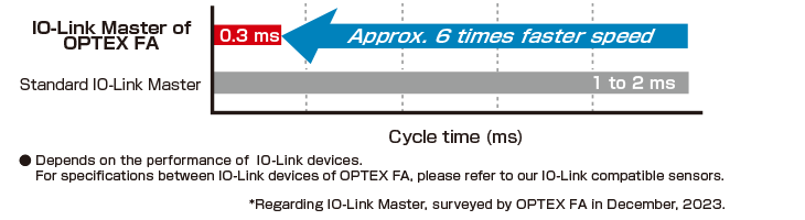
Realized the minimum cycle time of 0.3 ms
The IO-Link minimum cycle time achieves the industry's fastest* high-speed response of 0.3 ms.
The response time issue of IO-Link communication has been resolved.
Realization of palm size
Approx. 1/2 the size (W110 x D31.4 x H63 mm) of a standard IO-Link Master (8 channels).
In addition, the number of channels is doubled, which contributes to space saving in the equipment.
- In IO-Link Master with display and operation unit.
Surveyed by OPTEX FA in December, 2023.
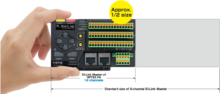
Palm sized unit with 16 IO-Link ports
10 languages supported
Ten languages can be easily selected in the system menu.
The global design allows for safe and reliable use even when equipment is moved overseas.

Automatic IODD download function
Using IO-Link Master and IO-Link devices of OPTEX FA eliminates the need to configure IODD files.
Supports 7 field networks
The multi-protocol design of this unit can be easily switched industrial Ethernet in the system menu.

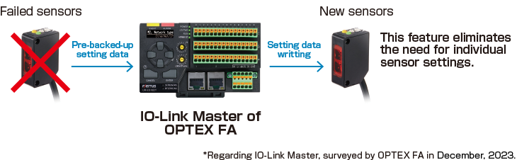
Backup / restore
When replacing a sensor, if a sensor of the same model is connected to the same terminal position, the settings before the replacement are automatically written.
No sensor reconfiguration is required, which saves downtime.
Users want real ease of use
OPTEX FA's IO-Link Master is equipped with an OLED display and operation keys that allow users to check, set, and change IO-Link device parameters, maintenance information, and errors without using a PC or HMI.
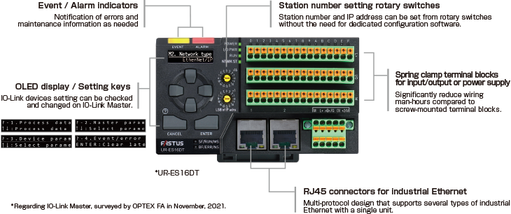
Easy configuration
Accurate data collection
Larger buttons with the tilted top shape help operators easy setting of parameters.
Easy setup
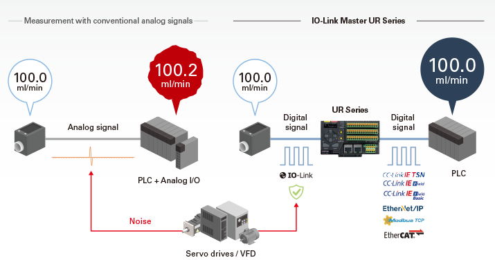
Parameter settings for IO-Link pressure and flow sensors can be set from a host on the network. This reduces the possibility of sensor setting errors or unintentional setting omissions. The parameters once set can be backed up to the UR Series IO-Link Master. If the sensor is replaced with one of the same model, the setting information can be restored to avoid accidentally different information than before.

Miswire / Wire Break Detection
Any point that differs from the preconfigured connection information will be detected as a miswire. Even if power to an IO-Link device (sensor) is cut off due to a wire break, the determination signal of the sensor is maintained without interruption, and the wire break can be detected.

Multi-point / Distributed I/O Control
In addition to IO-Link type devices, sink (NPN) and source (PNP) input/output devices can be connected to the IO-Link Master, enabling effective use of remaining channels other than IO-Link type devices connection.
Optimal solutions for pressure sensors and flow sensors
What is IO-Link?
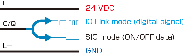
IO-Link is a technology that connects sensors and actuators to industrial Ethernet using digital signals.
Various types of data can be exchanged at the sensor level in line with the IIoT.

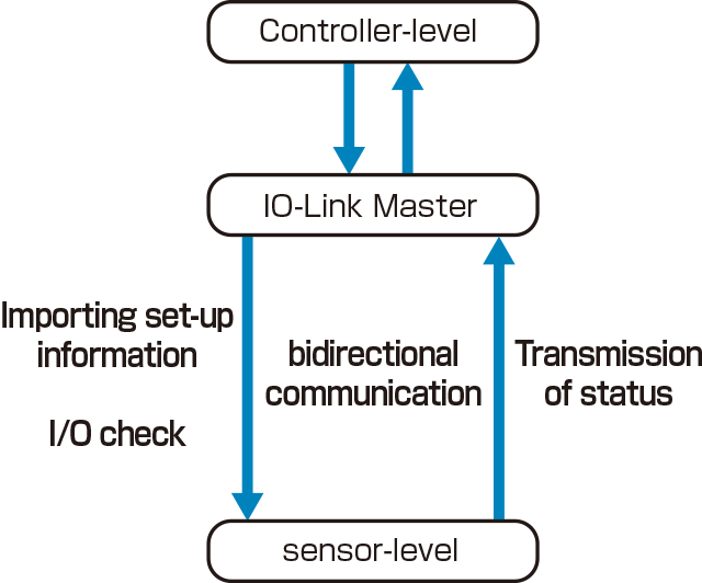
Easy sensor setup and status monitoring
Various types of data can be exchanged at the sensor level in line with the IIoT.
This means that batch sensor settings and I/O checks can be performed from the controller, and set-up information can be downloaded from IO-Link Master when replacing sensors.
An error display can also be set to indicate if the sensor is disconnected or otherwise malfunctioning.
As a result, equipment start-up / maintenance time can be reduced and sensor-level predictive maintenance can be performed.
System overview

Streamline equipment operation with IO-Link
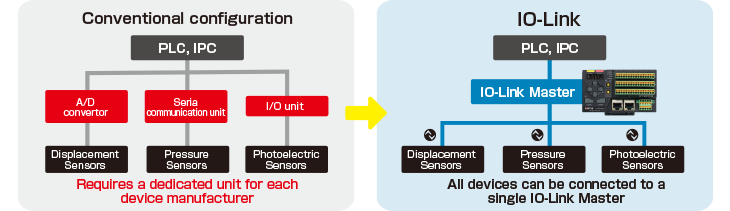
Contributes to space saving in the control panel
By converting digital, analog devices, and serial device to IO-Link, no communication program is required and input devices can be combined into an IO-Link Master.
Sensors and actuators that do not support IO-Link can also be connected, enabling ON/OFF control.
Standard sensor cables can be used
A standard 3-wire unshielded cable can be used for IO-Link communication, eliminating the need for a dedicated communication cable.
Firmware download for IO-Link Master UR Series
Firmware updates provide new features and improvements to existing functions.
Download List
Firmware corresponding to each version can be downloaded.
| Firmware version |
Functional improvements |
Connection procedure |
Download | |
|---|---|---|---|---|
| 1.06xxxx01 | - | - | CC-Link IE Field |
|
| CC-Link IE TSN |
||||
| 1.10xxxxxx (December 2024) |
- | - | CC-Link IE Field |
|
| Supports firmware version upgrade via direct LAN connection with a PC. | The direct connection may not be supported in all environments or under certain conditions. Refer to [Firmware Update Procedure Manual] for detail instructions. |
CC-Link IE TSN |
||
| 1.21xx40xx (March 2025) |
Expanded counter function
|
This update includes changes to the settings menu. The former menu "M15. Encoder input" will be changed to "M18. Pulse input". Configuration settings from the previous version will be automatically and seamlessly transferred to the updated menu item. |
CC-Link IE Field |
|
| CC-Link IE TSN |
| Firmware version |
Functional improvements |
Connection procedure |
Download | |
|---|---|---|---|---|
| 1.05xxxx01 | - | Do not perform a downgrade to this version on UR-EE units with Lot No. 2440L or later. | - | |
| 1.10xx40xx (December 2024) |
Expanded counter function
|
- | ||
| 1.12xx41xx (March 2025) |
Expanded counter function
|
This update includes changes to the settings menu. The former menu "M15. Encoder input" will be changed to "M18. Pulse input". Configuration settings from the previous version will be automatically and seamlessly transferred to the updated menu item. |
- | |
| (1.1220xxxx) | Dynamic allocation of input/output data size (process data length) is supported in EtherNet/IP implicit messaging.
|
Versions earlier than 1.xx19xxxx Versions 1.xx20xxxx or later After performing a firmware update, the correct EDS file should be selected based on the system environment. |
EtherNet/IP | |
| 1.1521xxxx (May 2025) |
"EtherNet/IP1.0.1" has been added to the "M2. Network type" option in the master parameter menu. When connecting via EtherNet/IP, you can now connect without reconfiguring the connection settings specified in the EDS file "UR-ES16DT V1.0.1.EDS" in the connection settings. |
Starting from this version, digital authentication is required for all tools that connect to the device. As tools without digital authentication will no longer be able to connect to the device, ensure the use of digitally authenticated tools from the versions listed below or newer. |
EtherNet/IP |
Prior to performing the firmware update
Each firmware version has its own specific limitations and precautions.
Prior to performing a firmware update, verify all applicable limitations and precautions. Select the firmware version that aligns with your system environment and operational requirements before proceeding.
Precautions when updating firmware
- It is essential to refer to the [Firmware Update Procedure Manual] and follow the specified steps carefully to avoid compatibility issues during the update process.
Failure to follow the correct procedure may lead to product failure or permanent damage. - Perform firmware update in the environment where the power does not turn off during the update process. If the power turns off during the update, there is a risk that this product may stop functioning.
In that case, please contact your point of purchase for assistance. - If an Ethernet communication error occurs during the update, do not turn off the power of the device.
Instead, perform the update again.
Supported features by firmware version
This list provides an overview of the additional and enhanced features supported in each firmware version.
| Firmware version |
Function | |||
|---|---|---|---|---|
| Network type | Supports firmware version upgrade via direct LAN connection with a PC |
Expanded counter function
|
Expanded counter function
|
|
| 1.06xxxx01 | CC-Link IE Field | |||
| CC-Link IE TSN | ||||
| 1.10xxxxxx | CC-Link IE Field | |||
| CC-Link IE TSN | ✓ | |||
| 1.21xx40xx | CC-Link IE Field | ✓ | ||
| CC-Link IE TSN | ✓ | ✓ | ||
| Firmware version |
Function | ||||
|---|---|---|---|---|---|
| Network type | Expanded Counter function
|
Dynamic allocation of input/output data size (process data length) is supported in EtherNet/IP implicit messaging |
Expanded counter function
|
Compatible with connection settings defined in "UR-ES16DT V1.0.1.EDS" |
|
| 1.05xxxx01 | - | ✓ | |||
| 1.10xx40xx | - | ✓ | ✓ | ||
| 1.12xx41xx (1.1220xxxx) |
- (EtherNet/IP) |
✓ | ✓ | ✓ | |
| 1.1521xxxx | EtherNet/IP | ✓ | ✓ | ✓ | ✓ |
EtherNet/IP connection settings after firmware update
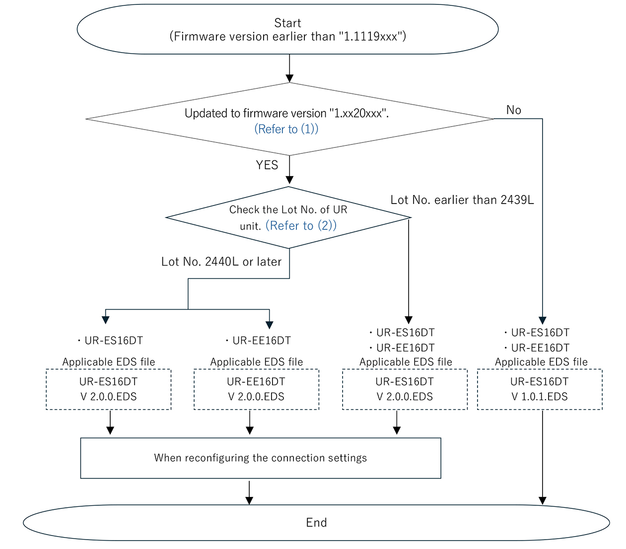
If the firmware is updated from version earlier than "1.1119xxxx" to "1.1220xxxx" or later while using EtherNet/IP, the existing connection settings may no longer be valid, and communication may fail.
After updating the firmware, please follow one of the connection flowcharts below according to your system environment to establish an EtherNet/IP connection.
When reconfiguring the connection settings using the appropriate EDS file
Select the appropriate EDS file based on your system environment, and configure the EtherNet/IP connection accordingly.
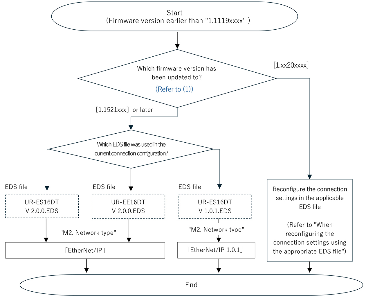
When connecting without changing existing connection settings
(Firmware version "1.1521xxxx" or later)
The master configuration of UR unit, “M2. Network type,” allows you to use the existing connection settings used before the update without having to replace the EDS file.
(1) Check the firmware version
- After turning on the device, check the information shown on the display.
- Show the "?-2. Master Settings Menu" on the display.
- Show the "M60. Version No."
- Check the firmware version number.
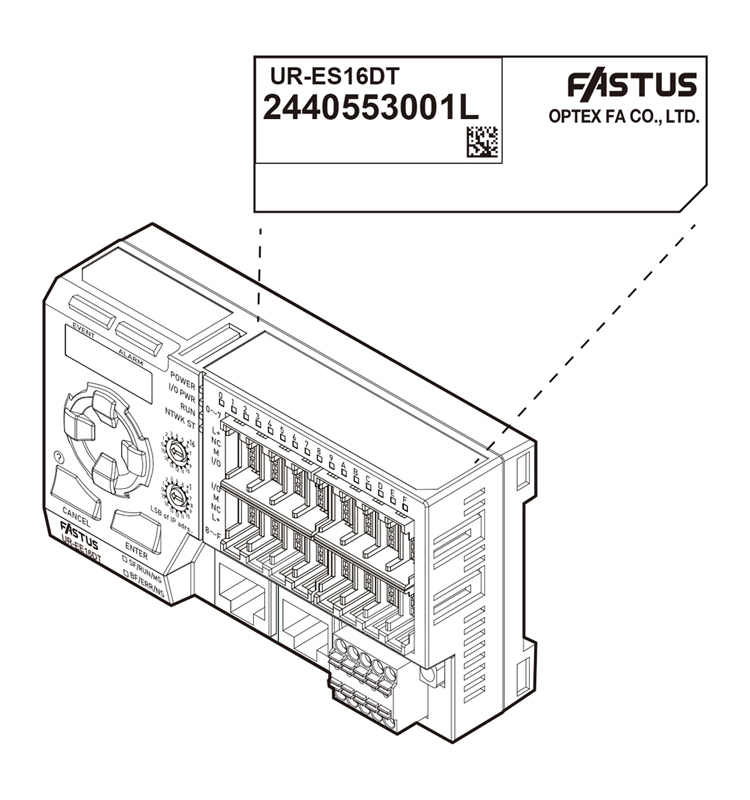
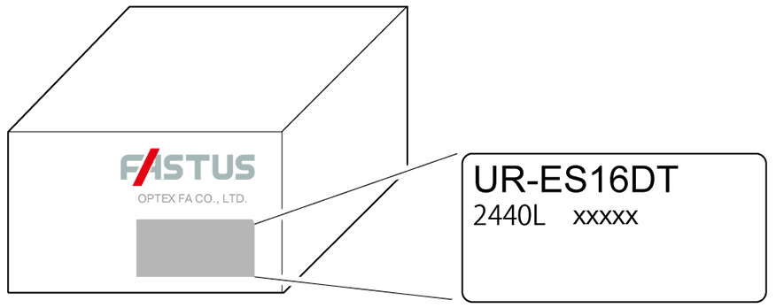
(2) Check the device lot number
The following methods can be used for verification:
- Refer to the label attached to the device.
Refer to the 11-digit* number printed on the top surface of the device.
- If the label shows a number in the format "2440xxxxxxL", the Lot No. is "2440L".
- Refer to the 5-digit number printed on the outer box of the device.
IO-Link devices of OPTEX FA
Non-Contact Thermometer TI-S Series
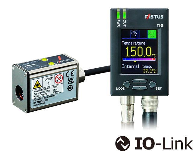
- Designed to be less susceptible to ambient temperature changes
- Ring laser pointer for visual confirmation of field of view
- Easy-to-read full color display
| IO-Link version | 1.1.3 | |
|---|---|---|
| Communication speed | COM3 (230.4kbps) | |
| Process data | Cycle time* | 0.5 ms |
| Input: 4 bytes → IO-Link Master |
|
|
| Output: 1 byte IO-Link Master → |
|
|
| Device data |
|
|
- The cycle time between OPTEX FA IO-Link Master UR Series and this device
M18 Cylindrical Non-contact Thermometers SA-80T-4IO
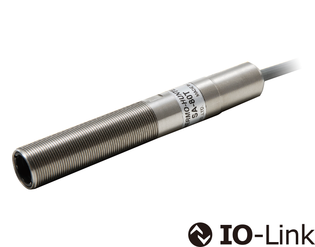
- Measurement values can be obtained as digital values.
- No need for analog I/O
| IO-Link version | 1.1 | |
|---|---|---|
| Communication speed | COM3 (230.4 kbps) | |
| Process data | Cycle time* | 3.0 ms |
| Input: 4 bytes → IO-Link Master |
|
|
| Output: 0 bytes | − | |
| Device data |
|
|
- The cycle time between OPTEX FA IO-Link Master UR Series and this device
Laser Displacement Sensors CD2H Series
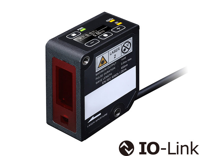
- Measurement values can be obtained as digital values.
- No conversion errors caused by D/A conversion, resulting in highly accurate measurements.
| IO-Link version | 1.1 | |
|---|---|---|
| Communication speed | COM3 (230.4 kbps) | |
| Process data | Cycle time* | 0.7 ms |
| Input: 6 bytes → IO-Link Master |
|
|
| Output: 0 bytes | − | |
| Device data |
|
|
- The cycle time between OPTEX FA IO-Link Master UR Series and this device
TOF Sensors TOF-DL250GC
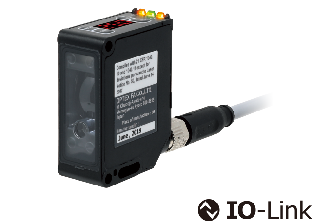
- Measurement values can be obtained as digital values.
- No need for analog I/O
| IO-Link version | 1.1 | |
|---|---|---|
| Communication speed | COM3 (230.4 kbps) | |
| Process data | Cycle time* | 1.0 ms |
| Input: 4 bytes → IO-Link Master |
|
|
| Output: 0 bytes | − | |
| Device data |
|
|
- The cycle time between OPTEX FA IO-Link Master UR Series and this device
Fiber-Optic Sensors D4RF Series (Stand-alone type)
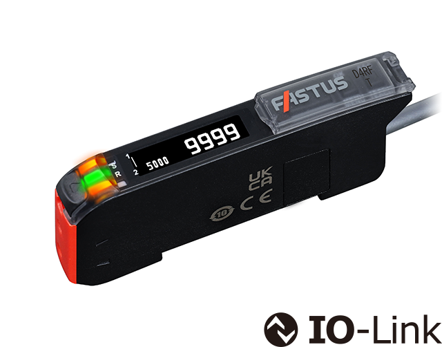
- Predictive notification of maintenance timing based on decrease in receiving light amount
| IO-Link version | 1.1 | |
|---|---|---|
| Communication speed | COM3 (230.4 kbps) | |
| Process data | Cycle time* | 0.5 ms |
| Input: 4 bytes → IO-Link Master |
|
|
| Output: 0 bytes | − | |
| Device data |
|
|
- The cycle time between OPTEX FA IO-Link Master UR Series and this device
Amplifier Built-in Sensors Z4/Z4B Series
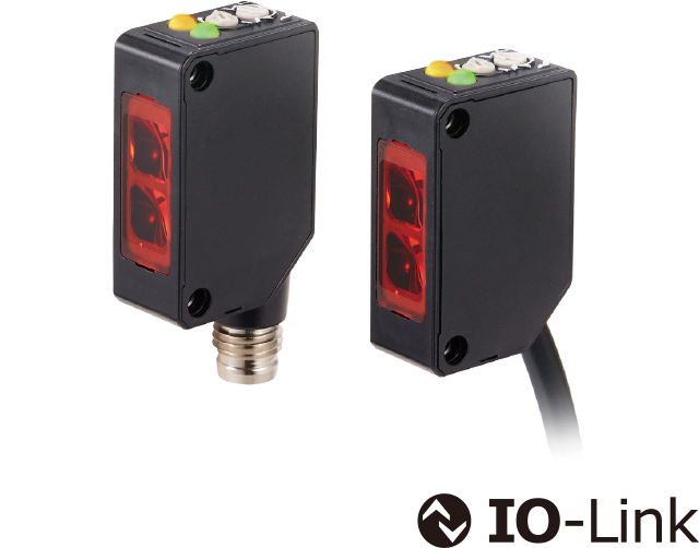
- Predictive notification of maintenance timing based on receiving light amount decline
| IO-Link version | 1.1 | |
|---|---|---|
| Communication speed | COM3 (230.4 kbps) | |
| Process data | Cycle time* | 0.5 ms |
| Input: 2 bytes → IO-Link Master |
|
|
| Output: 0 bytes | − | |
| Device data |
|
|
- The cycle time between OPTEX FA IO-Link Master UR Series and this device
IO-Link Gateway UC2-IOL
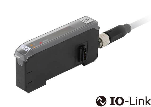
- Connect up to 16 units of our non-IO-Link compatible sensors to IO-Link
| IO-Link version | 1.1 | |
|---|---|---|
| Communication speed | COM3 (230.4 kbps) | |
| Process data | Cycle time* | 2.2 ms |
| Input: 32 bytes → IO-Link Master |
|
|
| Output: 0 bytes | − | |
- The cycle time between OPTEX FA IO-Link Master UR Series and this device
UC2-IOLconnectable sensors
Through-beam Edge Laser Sensors TD1 Series
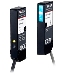
- Suitable for edge measurement and width/gap measurement
- Light axis alignment function for easy installation
- Compact design (W 9.6 x D 21 x H 61 mm)
- Separate amplifier unit CDA Series required
Laser Displacement Sensors CD22 Series
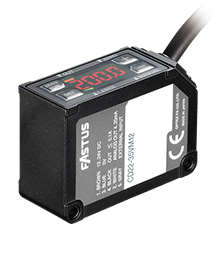
- Built-in amplifier & digital 4-digit display
- Featuring high performance functionality like high-end models
- CC-Link communication unit and connectable unit available
- Separate amplifier unit CDA Series required
White LED Fiber-Optic Sensors D3WF Series
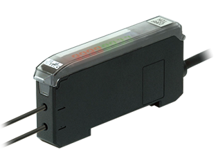
- White light source enables easy detection of subtle color differences
- Dual sensitivity correction for stable operation
- 100% display for better recognition of level change
- Separate amplifier unit CDA Series required
Fiber-Optic Sensors D4RF Series (when multiple units are connected)
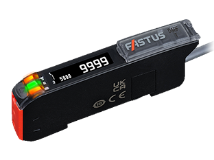
- Easy-to-read OLED display
- Fiber insertion indicators for instant verification
- Large LED Indicators
Contact Us
Our experts quickly deliver the best plan for your needs and provide continuous support throughout the process.
- Download List
- 20