

Setup tool for IO-Link Master UR Series
UR Explorer
A comprehensive tool for configuring and monitoring UR-MS, UR-ME, UR-ES, and UR-EE Series in a unified interface
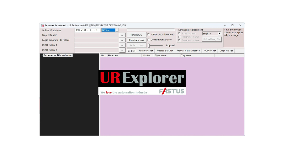
- Provides functionality for monitoring and validating configuration parameters and process data of IO-Link devices
- Supports search and installation IODD files provided by various vendors
- Supports backup and restoration UR Series and IO-Link devices
This comprehensive tool streamlines the configuration of both IO-Link Master UR-ES/-EE/-MS/-ME Series and its connected IO-Link devices.
Building on the capabilities of the existing UR Master Manager, it provides full access to essential functions such as editing device settings and backing up configuration files.
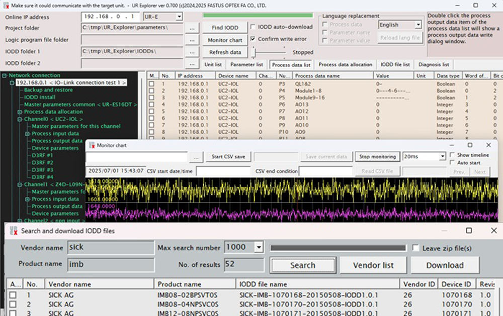
- Configuration
- Search and download of IODD files
- IO-Link device setup
- Process data allocation
- Test/Monitor
- Trend graph display for process data
- Force writing of process output data
- Operation
- IO-Link communication diagnostics
- Backup/Restore
- Remote operation of UR-MS/-ME/
-ES/-EE Series units
Feature 1: Automatic Search and Download of IODD Files
With a built-in IODD search function, UR Explorer eliminates the need for manual file searches, enabling users to easily locate IODD files directly through the interface.
IODD files for connected IO-Link devices can be automatically searched, downloaded, and installed.
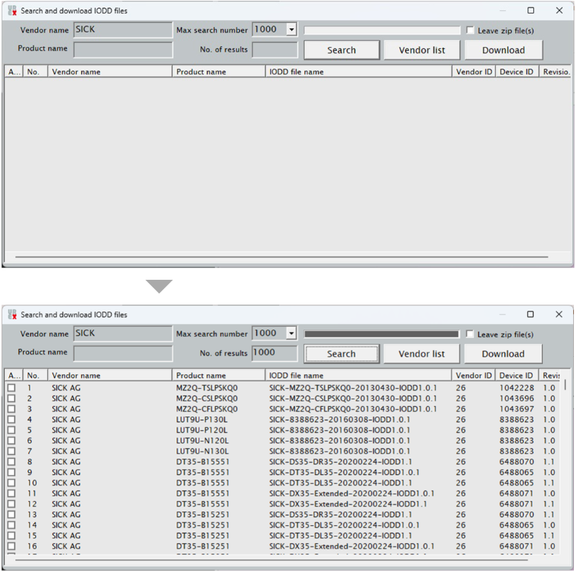
- Enter the vendor name of the
sensor to search. - Automatically list applicable IODD files
for the sensor via the network.
Feature 2. Process Output Data can be Configured
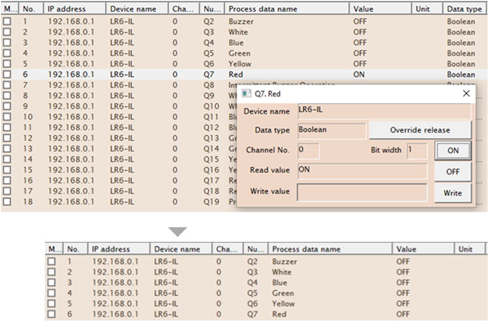
In addition to monitoring process input data, editing of process output data is also possible.
No host control is needed during I/O checks.
- Currently, only UR-E□16DT supports writing process output data.
Please note that UR-M□16DT does not support this function at this time.
Function List
| Function | Contents |
|---|---|
| Automatic search and download of IODD files | Batch download and installation of IODD files is available for various vendors and device models. |
| Configuration of IO-Link devices | Enables assignment of IO-Link devices, parameter list viewing, and setting modifications per master channel. |
| Parameters of IO-Link devices can be mapped to process data, and the configuration settings can be exported to a CSV file. | |
| Offline/Online mode | The following configuration options are available in both offline and online modes.
|
| Process data handling |
|
| Pulse input | Pulse input counter values can be monitored. |
| Diagnostics | This function diagnoses the Ethernet network status via a PC, the communication status with IO-Link devices, and the output overcurrent detection status. |
| Remote operation | This tool enables remote operation of the UR units. |
IO-Link Master UR Series
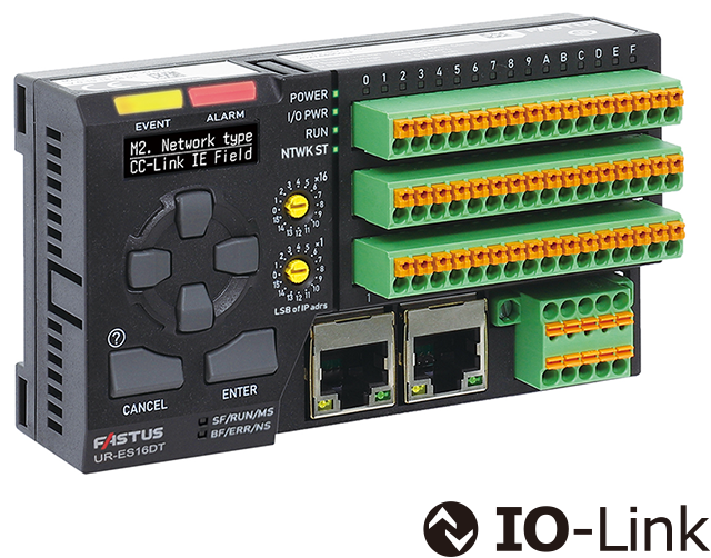
- First in industry* Mixed connection of digital Sink(NPN)/Source(PNP) I/O devices is realized with one unit
- Largest no. in industry* 16 channels
- Fastest in industry* Realized the minimum cycle time of 0.3 ms
- Regarding IO-Link Master, surveyed by OPTEX FA in December, 2023.
IO-Link Hub UR-DS Series
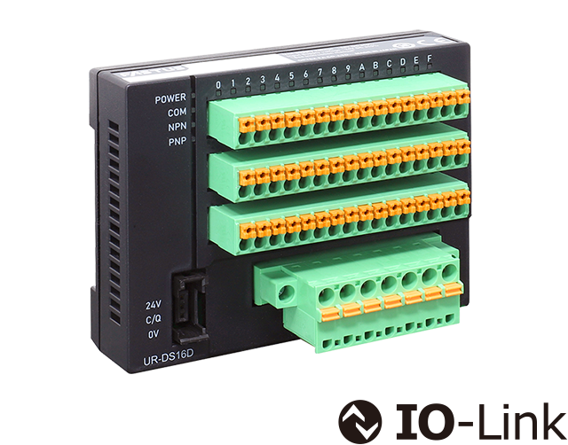
- IO-Link Hub connecting to an IO-Link Master, supporting Digital I/O, Analog I/O, and Temperature inputs
- IO-Link Hubs that can support digital inputs or outputs up to 256 points
(16 channels x 16 points) *When connected to the OPTEX FA UR Series. - By connecting to an IO-Link Master, various I/O functions can be expanded. This distributed configuration contributes to space-saving, reduced wiring, and improved noise resistance.
- A new IO-Link Hub supporting RTD input is now available. It allows temperature measurement using pt100 RTD sensors, with data transmitted and monitored via IO-Link communication.
IO-Link devices of OPTEX FA
Non-Contact Thermometer TI-S Series
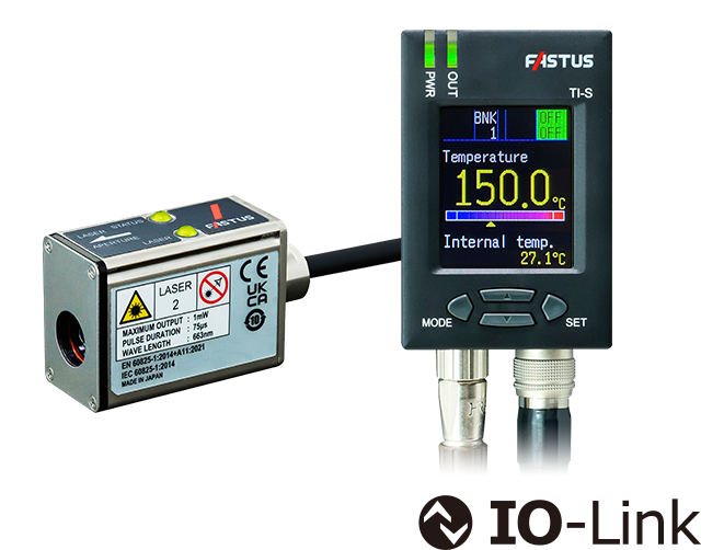
- Designed to be less susceptible to ambient temperature changes
- Ring laser pointer for visual confirmation of field of view
- Easy-to-read full color display
| IO-Link version | 1.1.3 | |
|---|---|---|
| Communication speed | COM3 (230.4kbps) | |
| Process data | Cycle time* | 0.5 ms |
| Input: 4 bytes
→ IO-Link Master |
|
|
| Output: 1 byte
IO-Link Master → |
|
|
| Device data |
|
|
- The cycle time between OPTEX FA IO-Link Master UR Series and this device
M18 Cylindrical Non-contact Thermometers SA-80T-4IO
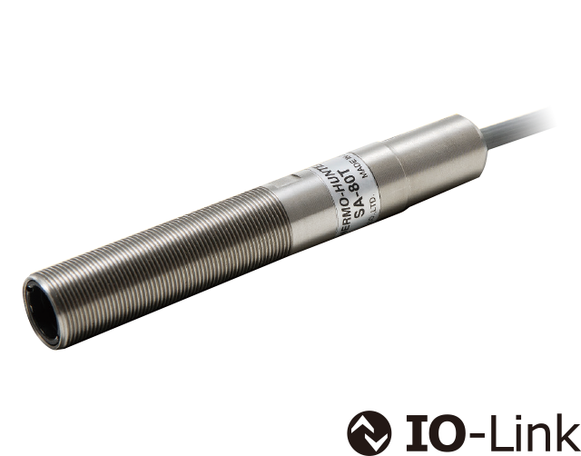
- Measurement values can be obtained as digital values.
- No need for analog I/O
| IO-Link version | 1.1 | |
|---|---|---|
| Communication speed | COM3 (230.4 kbps) | |
| Process data | Cycle time* | 3.0 ms |
| Input: 4 bytes → IO-Link Master |
|
|
| Output: 0 bytes | − | |
| Device data |
|
|
- The cycle time between OPTEX FA IO-Link Master UR Series and this device
Laser Displacement Sensors CD2H Series
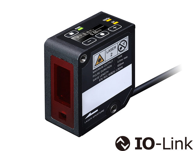
- Measurement values can be obtained as digital values.
- No conversion errors caused by D/A conversion, resulting in highly accurate measurements.
| IO-Link version | 1.1 | |
|---|---|---|
| Communication speed | COM3 (230.4 kbps) | |
| Process data | Cycle time* | 0.7 ms |
| Input: 6 bytes → IO-Link Master |
|
|
| Output: 0 bytes | − | |
| Device data |
|
|
- The cycle time between OPTEX FA IO-Link Master UR Series and this device
TOF Sensors TOF-DL250GC
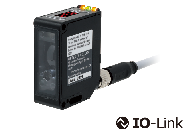
- Measurement values can be obtained as digital values.
- No need for analog I/O
| IO-Link version | 1.1 | |
|---|---|---|
| Communication speed | COM3 (230.4 kbps) | |
| Process data | Cycle time* | 1.0 ms |
| Input: 4 bytes → IO-Link Master |
|
|
| Output: 0 bytes | − | |
| Device data |
|
|
- The cycle time between OPTEX FA IO-Link Master UR Series and this device
Fiber-Optic Sensors D4RF Series (Stand-alone type)
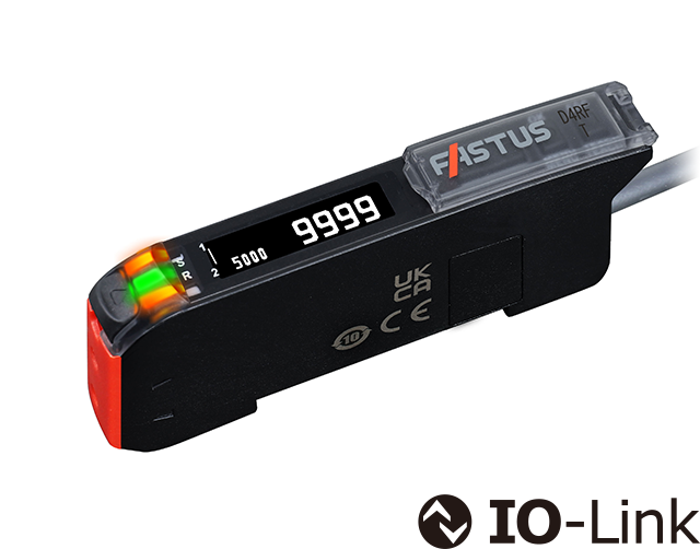
- Predictive notification of maintenance timing based on decrease in receiving light amount
| IO-Link version | 1.1 | |
|---|---|---|
| Communication speed | COM3 (230.4 kbps) | |
| Process data | Cycle time* | 0.5 ms |
| Input: 4 bytes → IO-Link Master |
|
|
| Output: 0 bytes | − | |
| Device data |
|
|
- The cycle time between OPTEX FA IO-Link Master UR Series and this device
Amplifier Built-in Sensors Z4/Z4B Series
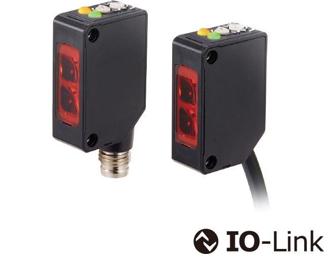
- Predictive notification of maintenance timing based on receiving light amount decline
| IO-Link version | 1.1 | |
|---|---|---|
| Communication speed | COM3 (230.4 kbps) | |
| Process data | Cycle time* | 0.5 ms |
| Input: 2 bytes → IO-Link Master |
|
|
| Output: 0 bytes | − | |
| Device data |
|
|
- The cycle time between OPTEX FA IO-Link Master UR Series and this device
IO-Link Gateway UC2-IOL
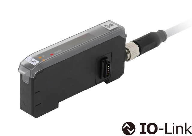
- Connect up to 16 units of our non-IO-Link compatible sensors to IO-Link
| IO-Link version | 1.1 | |
|---|---|---|
| Communication speed | COM3 (230.4 kbps) | |
| Process data | Cycle time* | 2.2 ms |
| Input: 32 bytes → IO-Link Master |
|
|
| Output: 0 bytes | − | |
- The cycle time between OPTEX FA IO-Link Master UR Series and this device
UC2-IOL connectable sensors
Through-beam Edge Laser Sensors TD1 Series
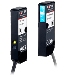
- Suitable for edge measurement and width/gap measurement
- Light axis alignment function for easy installation
- Compact design (W 9.6 x D 21 x H 61 mm)
- Separate amplifier unit CDA Series required
Laser Displacement Sensors CD22 Series
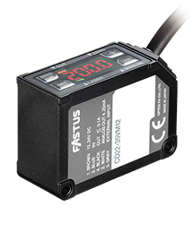
- Built-in amplifier & digital 4-digit display
- Featuring high performance functionality like high-end models
- CC-Link communication unit and connectable unit available
- Separate amplifier unit CDA Series required
White LED Fiber-Optic Sensors D3WF Series
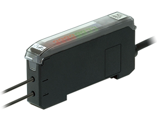
- White light source enables easy detection of subtle color differences
- Dual sensitivity correction for stable operation
- 100% display for better recognition of level change
- Separate amplifier unit CDA Series required
Fiber-Optic Sensors D4RF Series (when multiple units are connected)
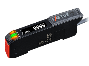
- Easy-to-read OLED display
- Fiber insertion indicators for instant verification
- Large LED Indicators
Contact Us
Our experts quickly deliver the best plan for your needs and provide continuous support throughout the process.
- Download List
- 20