

- Some models in this product series have been discontinued.
- Discontinued Models

Through-beam Edge Laser Sensors
TD1 Series
Edge Position Measurement for Any Workpiece




- Suitable for edge measurement and width/gap measurement
- Light axis alignment function for easy installation
- Easily readable amplifier unit Sold separately: CDA-DM2
Through-beam edge sensor TD1 Series devices use a CMOS sensor as the light receiving element, allowing for highly accurate edge position measurement of end surfaces.

Edge Measurement
The TD1 Series is ideal for equipment where edge control is required, such as for measurement of the end surfaces of components or sheet materials.

Width/Gap Measurement
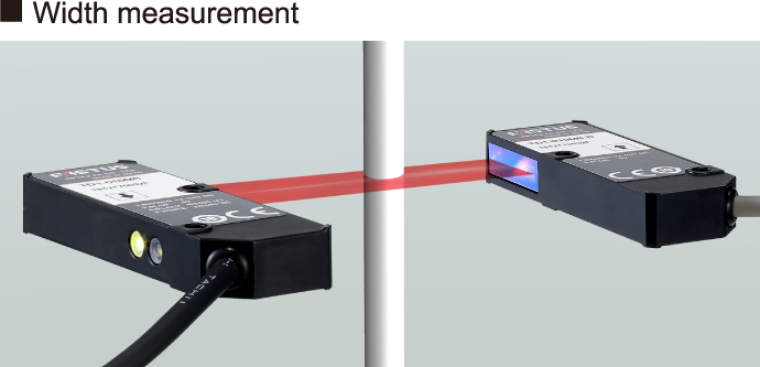
The measurement method used in a TD1 Series product can be changed to suit the inspection application, such as when measuring the width of small electronic components or the gaps between rollers.

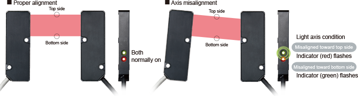
Easy Light Axis Alignment
In direction checking mode, the indicator will flash when the light axis is misaligned, notifying that the alignment should be checked.
This makes it easier to check the light axis when installing sensors or during periodic maintenance.
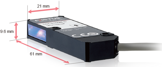
Compact Design
The compact size of the sensor head allows for easy installation even for devices with limited space. This makes it possible to keep equipment as small as possible.
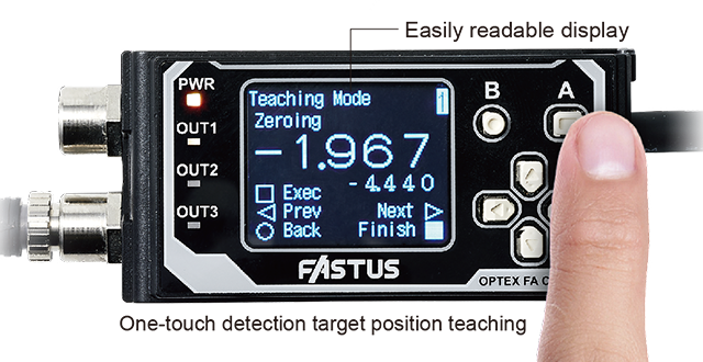
amplifier unit (Options)
Displacement sensor amplifier unit CDA Series
Features an organic EL display that can display clearly in both Japanese and English.
Calculations can be performed with up to two TD1 Series units.
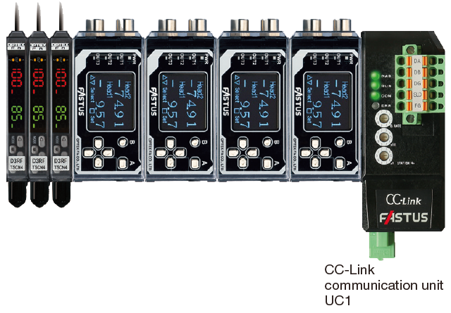
Connect with CC-Link to achieve “sensor visibility”
By connecting a CDA Series to a communication unit, connection to a CC-Link network is possible.
It supports Mitsubishi iQ Sensor Solution (iQSS) and batch management of sensors can be performed easily with GX Works2.

Simple Teaching Mode
When teaching, the edge center position can be set as desired within the measurement range. Simply place the measurement target and press the button.
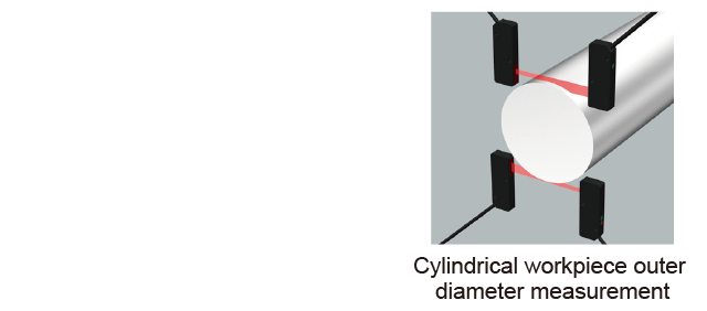
Calculation Function
Connecting two TD1 Series units enables measurement of workpieces with outer diameters of 10 mm or more..
CDA Series Specifications
| Type | 1 × analog output 2 × external inputs 3 × control outputs |
2 × high-resolution analog outputs 1 × external input 2 × control outputs |
||
|---|---|---|---|---|
| Main unit | Expansion unit | Main unit | ||
| Model | CDA-M | CDA-S | CDA-DM2 | |
| Sensor head (TD1 Series) |
Number of connectable sensors | Max. 2 sensors per CDA unit | ||
| Connection type | Amplifier side: M8, 4-pin connector | |||
| Communication I/F | RS-485 compliant (Overall cable length: Within 10m) | |||
| Rating | Supply voltage | 12 to 24 VDC ±10%, including 10% ripple (p-p) | Supplied from the main unit or UC1/UC2 *1 | 12 to 24 VDC ±10%, including 10% ripple (p-p) |
| Current consumption | 100 mA or less (at 12 V) |
100 mA or less (at 12 V) |
120 mA or less (at 12 V) |
|
| Display | Dot matrix display | OLED 128 x 96 pixels | ||
| Indicators | Power indicator (PWR): red/green, output indicators (OUT1/OUT2/OUT3): orange |
|||
| Analog output | No. of outputs | 1 | 1 | 2 |
| Type | 4 to 20 mA: Load impedance; 300 Ω or less |
4 to 20 mA: Load impedance; 300 Ω or less |
4 to 20 mA: Load impedance; 300 Ω or less 0 to 10 V: Output impedance; 100 Ω (selectable by setting) |
|
| Control output | No. of outputs | 3 | 3 | 2 |
| Type | NPN/PNP open collector (selectable by setting) Max. 100 mA/30 VDC, Residual voltage: 1.8 V or less |
|||
| External input | 2 inputs | 2 inputs | 1 input | |
| Environmental resistance |
Ambient temperature/humidity | -20 to +50℃ / 35 to 85% RH (no freezing or condensation) | ||
| Storage temperature/humidity | -20 to +60℃ / 35 to 85% RH (no freezing or condensation) | |||
| Vibration resistance | 10 to 55 Hz; double amplitude 1.5 mm; 2 hours in each of the X, Y, and Z directions |
|||
| Shock resistance | Approx. 50 G (500 m/s2), 3 times in each of the X, Y, and Z directions |
|||
| Protection circuit | Reverse connection protection, overcurrent protection | |||
| Degree of protection | IP50 (IEC 60529) | |||
| Applicable regulations |
EMC | EMC directive (2014/108/EU) | ||
| Environment | RoHS directive (2011/65/EU), China RoHS (Directive No. 32) | |||
| Applicable standards | EN 60947-5-7 | |||
| NRTL Certification | UL Recognized Components | |||
| Material | Polycarbonate | |||
| Weight (including cable) | Approx. 170 g | |||
- *1.Supply 12 to 24 VDC to the power wires (brown and blue) of the cable as the supply voltage for the compatible sensors.
Contact Us
Our experts quickly deliver the best plan for your needs and provide continuous support throughout the process.
- Download List
- 20