

Circuit Diagram
I/O Circuit Diagrams
IO-Link/analog output Type
-
NPN setting*1
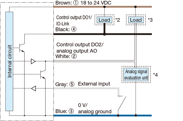
*1. When using NPN settings for an IO-Link connection, use OPTEX FA’s IO-Link Master UR Series or IO-Link Master with sink support.
*2. When used as control output DO1
*3. When used as control output DO2
*4. When used as analog output AO -
PNP setting
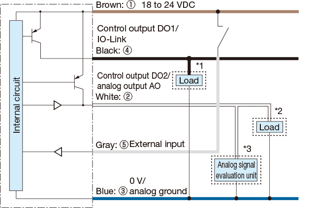
*1. When used as control output DO1
*2. When used as control output DO2
*3. When used as analog output AO
-
Push-pull setting
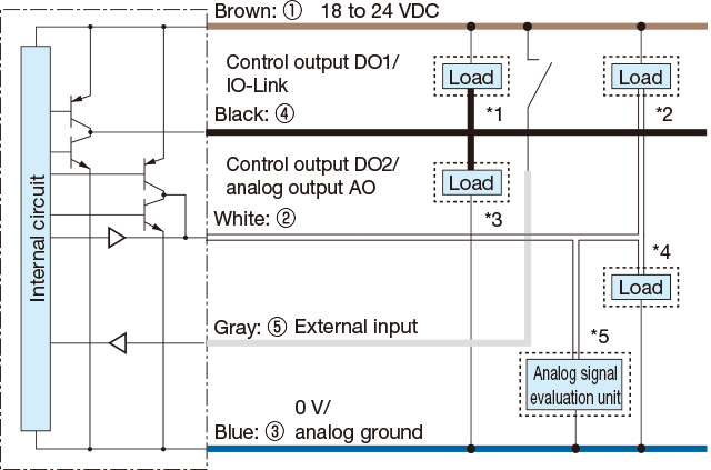
*1. When used as control output DO1 with NPN connection
*2. When used as control output DO2 with NPN connection
*3. When used as control output DO1 with PNP connection
*4. When used as control output DO2 with PNP connection
*5. When used as analog output AO -
M12 connector pin assignments

RS-485 Type
-
NPN setting (when load is connected by
NPN with the push-pull setting)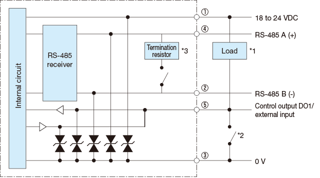
*1. When used as control output
*2. When used as external input
*3. Default setting for the termination resistor is ON.
When multi-drop connections are made, turn the termination resistor OFF at all units except the unit which is connected at the end. -
PNP setting (when load is connected by
PNP with the push-pull setting)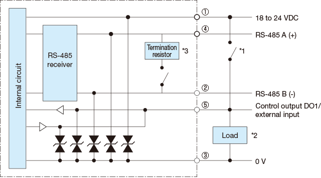
*1. When used as external input
*2. When used as control output
*3. Default setting for the termination resistor is ON.
When multi-drop connections are made, turn the termination resistor OFF at all units except the unit which is connected at the end.
-
6-wire twisted pair cable
(CD-MC1206-G□S)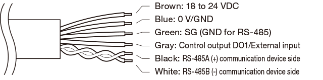
8-wire twisted pair cable for multi-drop
(CD-MC1208-G□M)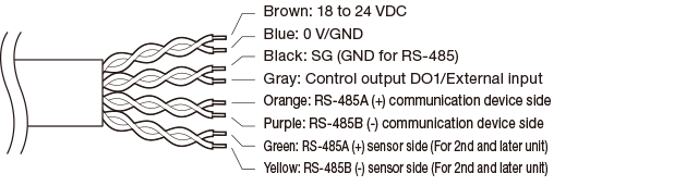
-
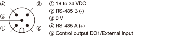
M12 connector pin assignments
Contact Us
Our experts quickly deliver the best plan for your needs and provide continuous support throughout the process.
- Download List
- 20