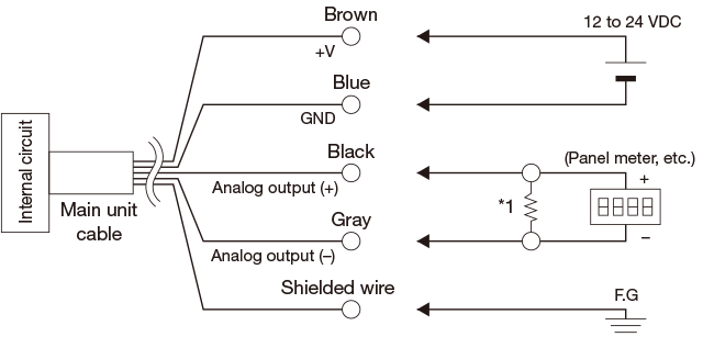
*1 Load resistance: 250 Ω or less (BA-30TA-S / BA-06TA-S、BA-30TV-S / BA-06TV-S only)
Notes regarding connections
GND and analog output (–) are connected internally. Be careful not to cause a short-circuit by applying voltage mistakenly.
For the meter and other products when connecting the analog output, use products with a power impedance of 100 kΩ or more. (BA-30TV-S/BA-06TV-S only)
When connecting analog output from a current output type (BA-30TA-S/BA-06TA-S) to a meter or other product, connect with a load resistance of 250 Ω or less (*1).
Do not connect the analog output (–) to GND or the like. Doing so will result in an error.
Do not short-circuit the analog output to any other output lines.
Using the same piping for parallel wiring with wiring input/ output lines, power lines, or high-voltage lines may cause malfunctions due to EMI noise. Use shielded wire or a separate metal conduit.
BA-30TC / BA-06TC
Notes regarding connections
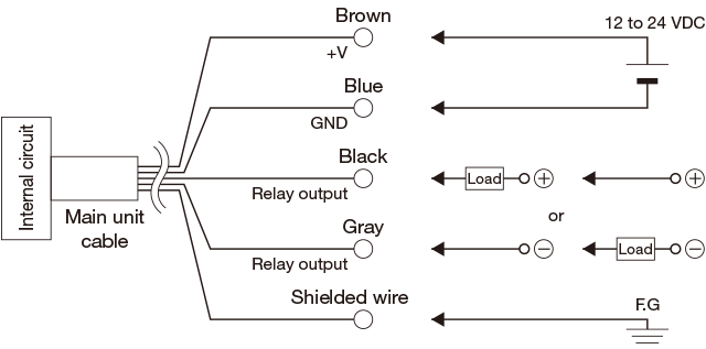
Use a power supply within the rated voltage range, and pay careful attention to polarity.
Do not short-circuit the relay output to any other output lines.
The relay output uses a photo MOS relay, so it is insulated from the circuit. The ON resistance is 2.5 Ω or less.
For use in environments with strong EMI noise, countermeasures such as passing the output cord through an iron pipe are necessary.
Output settings(BA-30TC / BA-06TC only)
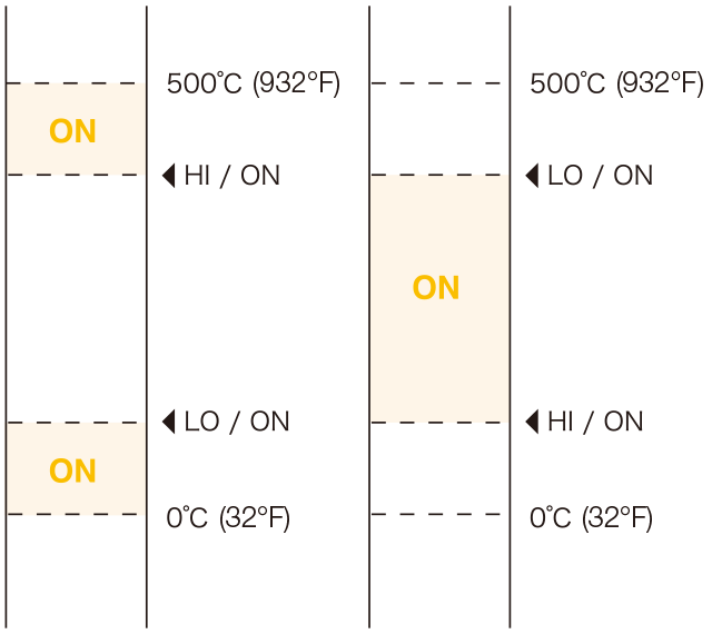
HI/ON: Output turns on when the measurement is equal to or greater than the setting.
LO/ON: Output turns on when the measurement is equal to or greater than the setting.
1. Align the menu bar to the HI/ON or LO/ON position, and then press the ENTER button.
2. Press the △ or ▽ button to change the setting, and then press the ENTER button to register the setting.
3. Press the △ or ▽ button to set ON (enabled) or OFF (disabled), and then press the ENTER button.
When setting to ON, output will be turned on when the ENTER button is pressed.
・During output, the ENTER button will illuminate at the same time the laser is irradiated.
When the HI setting is smaller than the LO setting, output will turn on only between HI and LO.
Contact Us
Our experts quickly deliver the best plan for your needs and provide continuous support throughout the process.