

Specifications
Technical Data
| Model | Without Ethernet | OPPX-6012P2 | OPPX-12012P4 | OPPX-1601224P4 | OPPX-10024P2 | OPPX-20024P4 | ||
|---|---|---|---|---|---|---|---|---|
| With Ethernet | OPPX-6012E2 | OPPX-12012E4 | OPPX-1601224E4 | OPPX-10024E2 | OPPX-20024E4 | |||
| Supply voltage | 24 VDC ±10% | |||||||
| Output channels | 2 ch | 4 ch | 2 ch (L1, L2) |
2 ch (L3, L4) |
2 ch | 4 ch | ||
| Connectable illumination ratings | All channels max. | 60 W | 120 W | 60 W | 100 W | 100 W | 200 W | |
| Max. per channel | 30 W/ch | 50 W/ch | ||||||
| Lighting output voltage | PWM mode | 12 VDC (standard) | 24 VDC (standard) | |||||
| STB mode*1 | 18 VDC | 48 VDC | ||||||
| DC mode | 8 to 12 VDC | Low: 12 to 24 V, High: 18 to 24 V | ||||||
| L-INT mode | 12 VDC | 24 VDC | ||||||
| L-INT STB mode*1 | 18 VDC | 36 VDC | ||||||
| Lighting output current | PWM / DC / L-INT mode | 2.5 A/ch | 2.0 A/ch | |||||
| STB / L-INT STB mode | 8.0 A/ch (duty 10%) | 5.0 A/ch (duty 7%) | ||||||
| Light intensity | PWM intensity control, Frequency: 50 kHz, 100 kHz, 130 kHz Voltage variable mode | PWM intensity control, Frequency: 100 kHz, 130 kHz Voltage variable mode | ||||||
| Strobe | Illumination time*1 | When PWM frequency 50 kHz is set: 20 μs to 19980 μs (in 20 μs steps), 1 ms to 999 ms (1 ms steps) When PWM frequency 100 kHz and 100 kHz DC are set: 10 μs to 9990 μs (in 10 μs steps), 1 ms to 999 ms (1 ms steps) When PWM frequency 130 kHz DC is set: 7.7 μs to 7684.6 μs (in 7.7 μs steps), 1 ms to 999 ms (in 1 ms steps) *When 1 ms is exceeded: Driven at 12 VDC for 12 V type, and 24 VDC for 24 V type |
||||||
| Flash cycle limit | 10% duty (10 times or more than the required pulse width cycle) | 7% duty (14.3 times or more than the required pulse width cycle) | ||||||
| Input | External synchronization control pin (SYNC1 to 4, SEQRST) |
When 5 V SYNC is OFF |
ON voltage: 12 to 24 V, OFF voltage: 1 V or less NPN Response time: OFF → ON within 2 μs, ON → OFF within 10 μs PNP Response time: OFF → ON within 2 μs, ON → OFF within 12 μs |
|||||
| When 5 V SYNC is ON |
ON voltage: 5 to 24 V, OFF voltage: 1 V or less |
|||||||
| External parallel control pin | Please refer to the user's manual. | |||||||
| Output | Multi-function outputs with customizable content: 6 points Photocoupler open collector output Max. 50 mA / 30 VDC, residual voltage 1.5 V (when 10 mA) |
|||||||
| Communication interfaces | USB (Full-speed, Type-C connector) |
Serial communication by virtual COM port | ||||||
| RS-232C | 4800/9600/19200/38400/57600/115200 bps | |||||||
| Ethernet (10BASE-T/100BASE-TX) *Only installed in OPPX-□□□□E□ |
UDP, TCP, DHCP, and iQSS (Mitsubishi Electric iQ Sensor Solution) | |||||||
| Ambient temperature/humidity | 0 to 40°C / 20 to 85% RH (no condensation) | |||||||
| Storage temperature/humidity | -20 to 70°C / 20 to 95% RH (no condensation) | |||||||
| Vibration resistance | 10 to 55 Hz, double amplitude 1.5 mm; 2 hours in each of the X, Y, and Z directions | |||||||
| Shock resistance | Approx. 10 G, 3 times in each of the X, Y, and Z directions | |||||||
| Material | Polycarbonate | |||||||
| Weight | 2 ch type: 260 g, 4 ch type: 360 g | |||||||
| Degree of protection | IP20 (IEC 60529) | |||||||
| Applicable regulations | EMC*2 | EU EMC directive (2014/30/EU) UK directive EMC (The Electromagnetic Compatibility Regulations 2016) |
||||||
| Environment |
EU RoHS directive (2011/65/EU), China RoHS (MIIT Order No.32) |
|||||||
| Applicable standards | EN IEC 61326-1 (Group 1, Class A according to EN 55011) | |||||||
| Design life | 7 years (maximum load, 24 hours continuous use, 40°C environment) | |||||||
| Accessories | External illumination control connector, power connector, instruction manual | |||||||
- *1.If the strobe illumination time exceeds 1 ms, the 12 V type will be driven at 12 VDC, and the 24 V type will be driven at 24 VDC.
- *2.If the light intensity value is set to 900 or higher, noise may increase depending on the user's cable wiring conditions.
In that case, attach a ferrite core to the end of the lighting output cable on this product side.
Recommended ferrite core: NFT-13S (Manufactured by TAKEUCHI INDUSTRY CO., LTD. Maximum cable diameter: 13.5 mm)
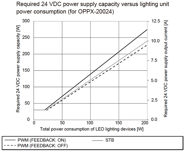
Required 24 VDC power supply capacity for power consumption of lighting unit
-
Based on the total power consumption of the LED lighting unit to be connected, select a 24 VDC power supply that offers more than the required capacity.
See the graph on the right.Note:
When using in conjunction with other equipment, the characteristics of theother equipment will affect the power supply, so be sure to choose a power supply that has a sufficient margin (about twice as much) as that shown inthe table. -
Contact Us
Our experts quickly deliver the best plan for your needs and provide continuous support throughout the process.
- Download List
- 20