

Circuit Diagram
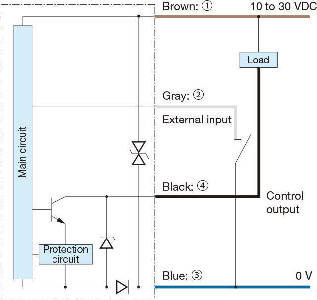
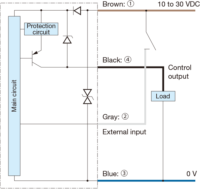
I/O circuit diagram
-
NPN output type
-
PNP output type
-
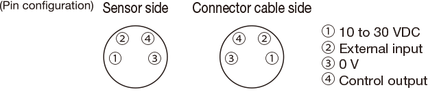
Connector type
-
Connecting
- When not used for external input, cut the lead wire and wrap it individually with insulating tape, and do not connect it to any other terminal.
- 1 to 4 are connector pin No.
Notes
- When using a switching regulator for the power supply, be sure to ground the frame ground terminal.
- Because wiring sensor wires with high-voltage wires or power supply wires can result in malfunctions due to noise, which can cause damage, make sure to wire separately.
- Avoid using the transient state while the power is on (approx. 100 ms).
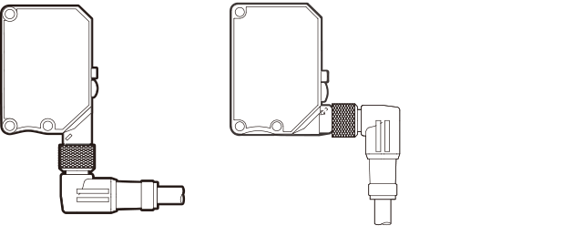
- The connector direction is fixed as in the drawing below when you use L-shaped connector cable. Be aware that rotation is not possible.
Operation mode

Contact Us
Our experts quickly deliver the best plan for your needs and provide continuous support throughout the process.
- Download List
- 20