

Circuit Diagram
-
NPN setting*1
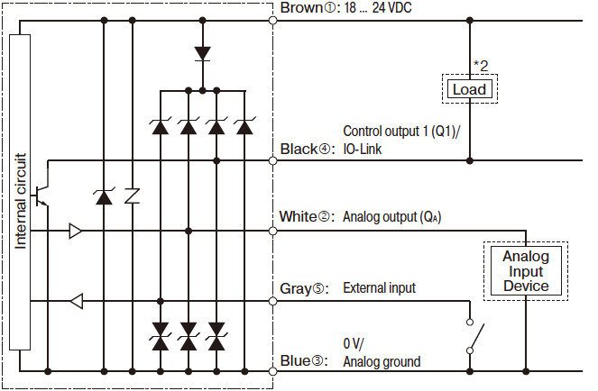
*1. When connecting to IO-Link with the NPN setting, use the IO-Link Master UR Series or a sink-type compatible IO-Link Master.
*2. When used as control output 1 (Q1) -
PNP setting
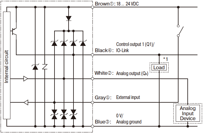
*1. When used as control output 1 (Q1)
-
Push-pull setting
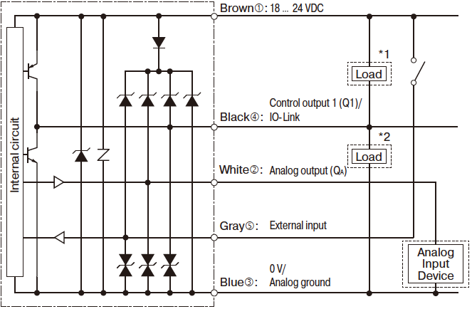
*1. When used as control output 1 (Q1) with NPN connection
*2. When used as control output 1 (Q1) with PNP connection -
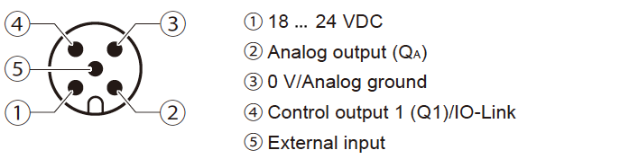
M12 connector pin assignments
Contact Us
Our experts quickly deliver the best plan for your needs and provide continuous support throughout the process.
- Download List
- 20