

Product Selection Guide
Sensor Selection Procedure
Step1 Checking Detection Details
First check the detection conditions. The general items that need to be checked are shown below.
Object to Detect
| Color | Are there variations from color (reflectance) to color? |
|---|---|
| Size | Does the size vary from one workpiece to another? |
| Shape | Are there variations in tilt and shape? |
| Gloss |
|
Background (No Object Present)
| Distance to the workpiece |
If the workpiece and the background are close, it is difficult for there to be a difference between the reflected light levels. →It is difficult to perform detections with diffuse types, so consider detection with a through-beam type or a BGS type. |
|---|---|
| Color |
Is the color difference with the workpiece sufficient? →If the workpiece is black and the background is white, the reflected light level may be equivalent. |
| Gloss |
Is the surface glossy or made of stainless steel? If the surface is glossy, is the environment one in which ambient light enters the sensor? |
Step2 Considering Detection Type
Consider the stable detection type that gives the largest difference with the background (the OFF status) when a workpiece is present (the ON status).
Consider the Detection Type.
Consider the sensor type.
The normal detection stability order among the different type is shown below. (The type with the highest stability is shown on the left.)
|
Through-beam > Retro-reflective > BGS/TOF > Diffuse-reflective |
Consider the Safest Type.
Consider the detection type that has the largest difference between when the workpiece is present and not present and that can perform stable detections.
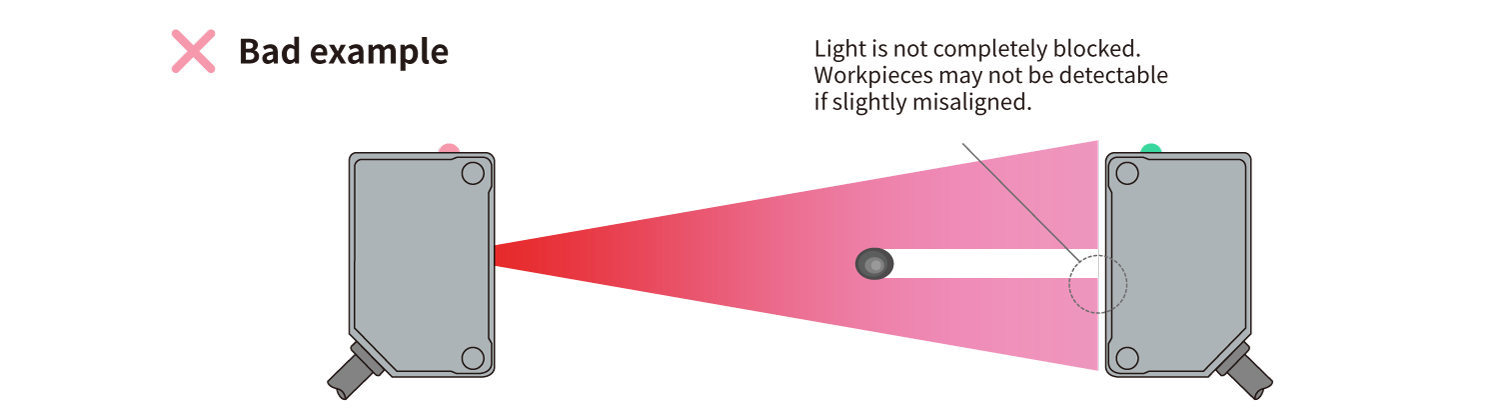
For example, when detecting a small workpiece like that shown below, using a fiber sensor leads to 100% of the light being blocked when the workpiece is present, which enables stable detection.

Step3 Verifying Other Conditions
Even if detection is possible, you have to exercise caution in checking whether a sensor can be used with the actual line.
The points that cause problems with actual lines are shown below. Be sure to check these points before using a sensor.
Checking the Line Speed (Response Time)
Check the takt and the line speed. With high-speed lines, perform tests using the actual line whenever possible. Exercise caution especially when using a fiber sensor to detect small workpieces because the detection time is short and a fast response is required.
| Response time calculation method |
Response time
=
Size of the object
Movement speed
|
|---|
〈Example〉
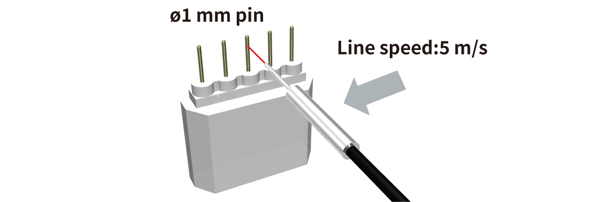
When detecting a pin with a diameter of 1 mm on a line that moves at a speed of 5 m/s, what should the response time be of the sensor that you select?
Ambient Environment
Check whether the ambient environment can be used according to the sensor specifications.
| Temperature | Sensors cannot be used in environments that are outside of their ambient temperature range. In high-temperature applications such as those inside of furnaces, use heat-resistant fibers. |
|---|---|
| Oil |
Oil penetrates the sensor more easily than water, and if it gets inside, the sensor will be damaged. Depending on the type of oil, sensors with IP67G (Z-M/BGS-ZM Series) may be suitable, so please contact OPTEX FA for more information. |
| Water/dust | The water and dust resistance is prescribed by the degree of protection (IP). However,even with a rating of IEC: IP67, a sensor cannot be used if it is submerged under water at all times. The IP indicates the water resistance against temporary water such as that during cleaning. |
| Noise | It is extremely rare for a sensor to be damaged by noise. However, strong noise may lead to signals turning ON and OFF being detected in a manner that is different than what it should be. Motors and inverters are sources of strong noise, so consider countermeasures such as changing the installation position and using shielding to block the noise if you suspect that noise is a problem. |
- Download List
- 20