

Correct Use
Cross-Talk Prevention
When photoelectric sensors are installed next each other, operation of a sensor may become unstable affected from light from another sensor.
In this situation, avoid interference with the measurements listed below.
- Use interconnection models of fiber-optic sensors.
- Separate the sensors not to get interfered, referring to a interference characteristic chart.
- Add a slit or polarizing filter on through-beam sensor.
- Install emitters and receivers of through-beam sensors or retro reflective sensors and reflectors in opposite orders.
* Pay attention that reflected light from an object of sensor does not enter to a receiver of next sensor.

Influence from Ambient Illuminance
Although photoelectric sensors are designed to use modulated light to avoid influence from ambient illuminance, entrance of light from a high frequency fluorescent lamp or sunlight to the front of a sensor may cause mis operation of the sensor.
Examples of Illuminance
| Clear-sky sunlight | 100,000lx |
|---|---|
| Cloudy-sky sunlight | 30,000lx |
| Factory and office lighting | 400~1,500lx |
Installation
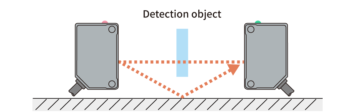
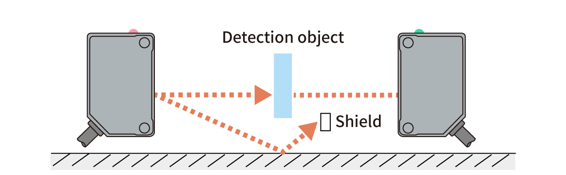
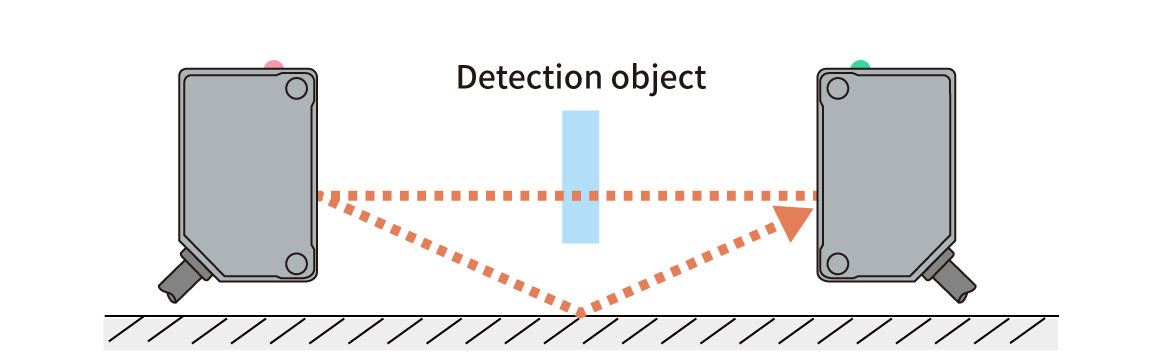
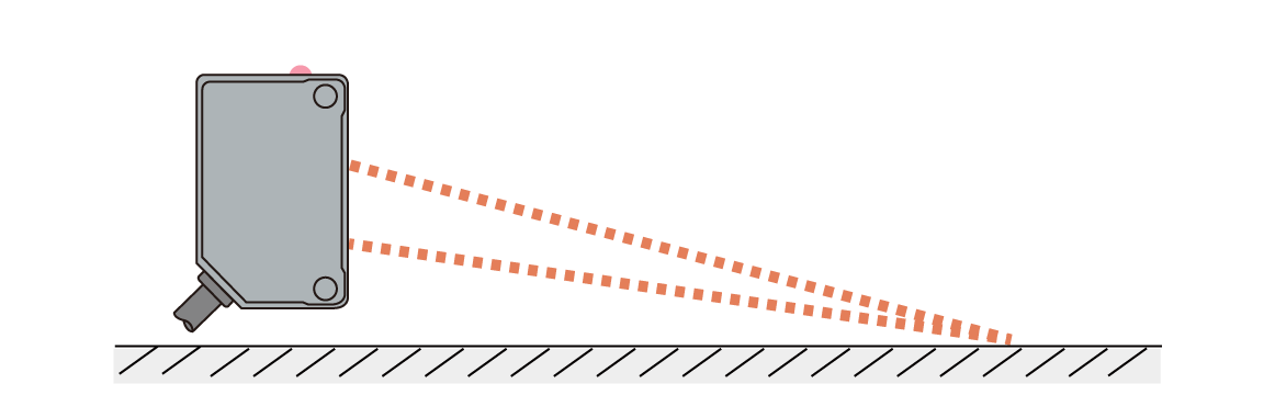
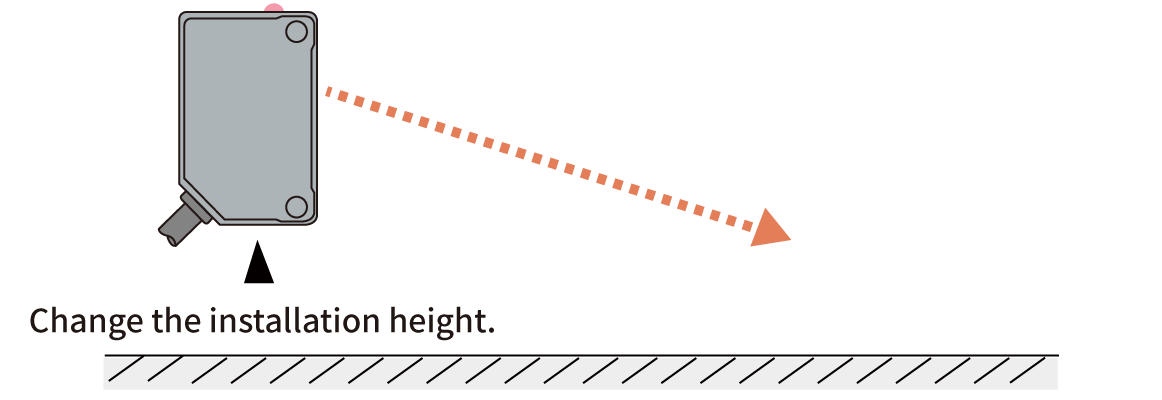
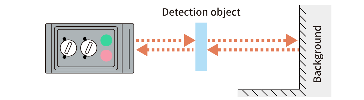
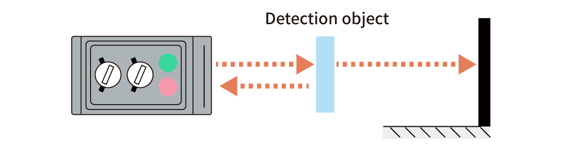
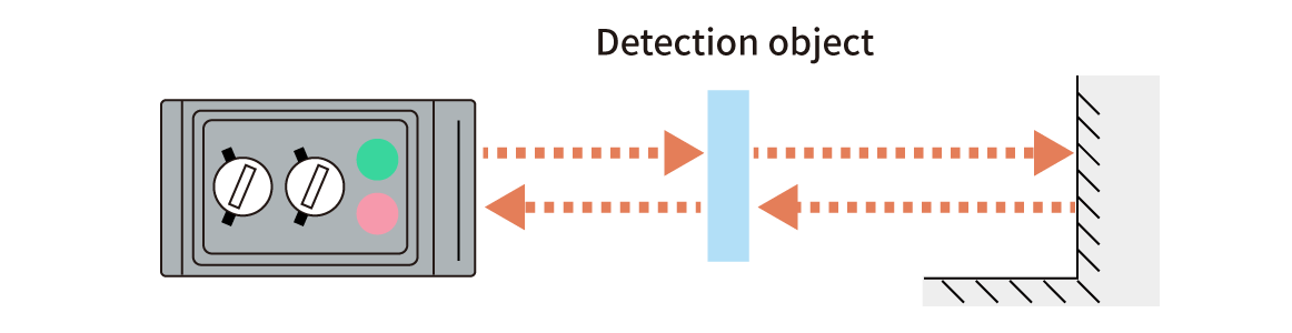
| Type | Problems | Solutions |
|---|---|---|
| Through-beam |
Receives light reflection from a surface below |
Place a shield to block reflected light. Mount the sensors at higher positions |
| Diffuse reflective |
Receives light reflection from a surface below |
Mount the sensors at higher positions |
|
Receives light reflection from background |
1. Paint the background in black to avoid light reflection. 2. Set detection objects away from the background 3. Use a BGS distance setting sensor. |
Light Axis Alignment
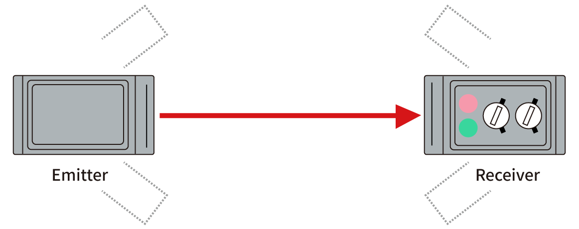
- Mount an emitter and receiver on a line facing each other.
- Move the emitter horizontally to confirm on angles, where the receiver receives light, then place the emitter at the center of angles.
- Move the receiver horizontally to confirm on angles, where the receiver receives light, then place the receiver at the center of angles.
- Repeat the same procedures in vertical directions.
General Cautions
- When using a switching power supply, make sure to connect its frame ground terminal to the ground.
- Upon power on, do not use a sensor during its warm-up time, for 100ms~2s depending on a sensor model.
- Do not place a sensor cable in parallel to or in a same cable guide with a high-voltage or power line.
Such installation may result in malfunction of the sensor caused by induction.
- Download List
- 20