

Dimensions
Unit: mm
-
Amplifier
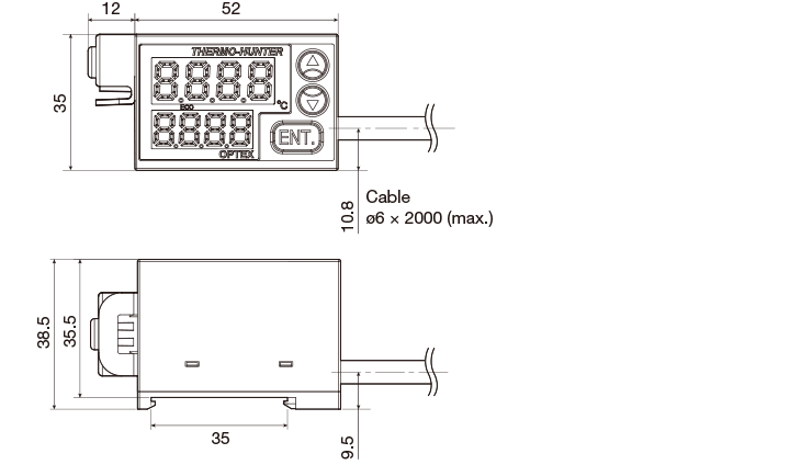
-
Sensor head
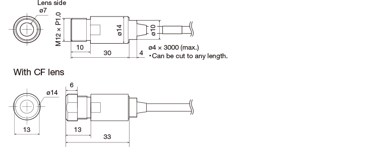
-
CF lens CS-CF01
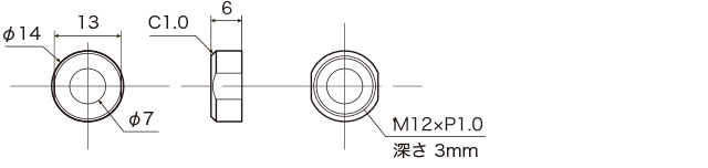
-
Laser marker CS-LDP
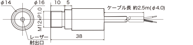
-
Air purge pipe CS-AP1
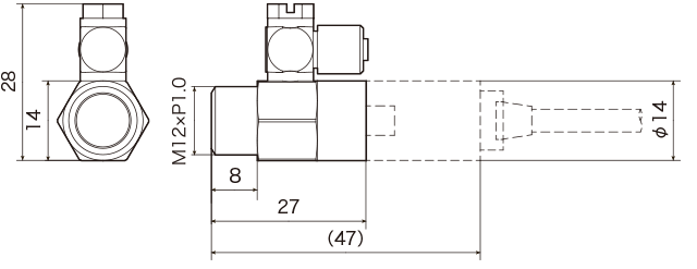
-
Mounting bracket CS-FB12
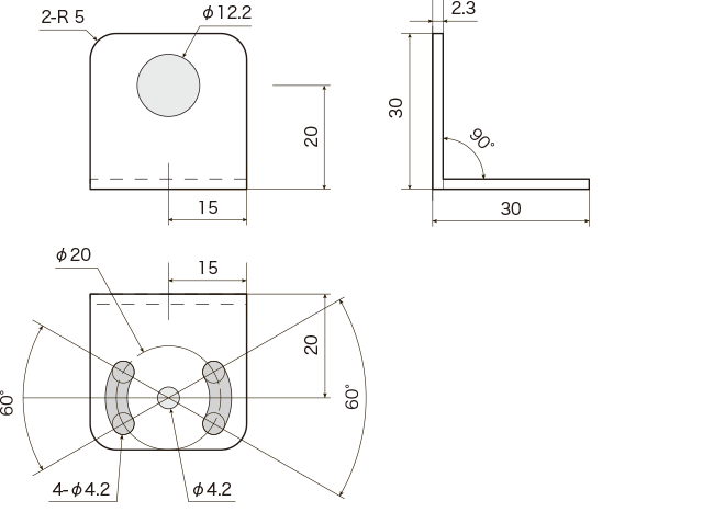
Wiring Diagram
-
Output cable


*1 Connect to the 4-20 mA input of an analog device.
Analog output allowable load 250Ω and analog output impedance 47 Ω
*2 External trigger: Switches on/off in the range from 2 to 5.
*3 Bank switch: Switches OPEN/CLOSE in the range from 2 to 6 or from 2 to 7 to select a bank. -

*4 When you cut the output cables shorter, a shielded cable for reinforcement will come out.
Cut the shielded cable to prevent it from contacting with other cables.
* Cables not used should be cut so that they do not contact with other cables, and insulated with adhesive tape or by other methods.
Contact Us
Our experts quickly deliver the best plan for your needs and provide continuous support throughout the process.
- Download List
- 20