

- Some models in this product series have been discontinued.
- Discontinued Models
Specifications
OPPF-48 Specifications
| Model | OPPF-48MN | OPPF-48MP | OPPF-48SN | OPPF-48SP |
|---|---|---|---|---|
| Type | Master device NPN output | Master device PNP output | Slave device NPN output | Slave device PNP output |
| Power supply voltage | 24 VDC ±10% | |||
| Current consumption |
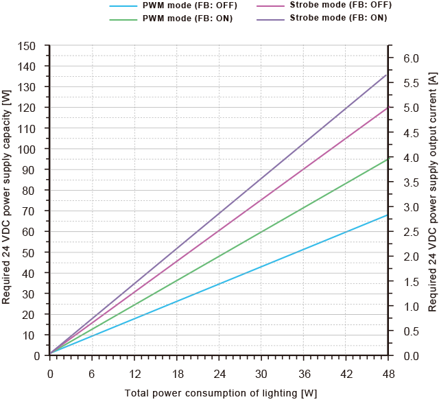
PWM mode ― Feedback OFF: Max. 2.9 A, Feedback ON: Max. 4.0 A Strobe mode ― Feedback OFF: Max. 5.0 A, Feedback ON: Max. 5.7 A |
|||
| Illumination output | 2 channels | |||
| Connectable lighting | PWM mode: Max. 48 W (2 ch total) *Max 30 W/ch, Strobe mode: Max. 24 W (per channel) | |||
| Illumination output voltage | PWM mode: 12 VDC (standard), Strobe mode: 18 VDC (standard) | |||
| Illumination output current | PWM mode: Max. 4.0 A (2 ch total), Strobe mode: 8.0 A (per channel) | |||
| Dimming method |
PWM dimming, Frequency: 20/50/100/99/98/97 kHz 1,000 steps *Common for PWM mode and strobe mode |
|||
| Strobe |
Luminescence width: 10 μs to 9.99 ms (10 μs steps) or 1 ms to 999 ms (1 ms steps) *12 VDC driving when exceeding 1 ms Flash cycle limit at 18 VDC: 10% Duty (10 times or more the pulse width cycle required) |
|||
| Monitoring |
Lighting brightness monitor / Lighting internal temperature monitor, Monitor brightness alarm lower limit value setting Update cycle per communication between lighting and power supply, Received light amount: 21 ms, Temperature: 105 ms |
|||
| Feedback |
Voltage variable method ― PWM mode: 11 to 18 VDC Strobe mode: 16 to 22 VDC, Accuracy: ±1.5% or less (typ.) *This specification is for reference only and is not a guarantee of the performance of this product. |
|||
| Input |
External illumination control × 2, Analog dimming select × 1, Parallel dimming input × 10 (bank select × 4 shared), Parallel dimming writing input × 1, Channel select input × 3 |
External illumination control × 2, Analog dimming select × 1 |
||
|
ON voltage: 5 V or more, OFF voltage: 1.2 V or less, Max. input voltage: 30 V Illumination control input response time (actual value) With 24 V input (OFF→ON: 5 μs, ON→OFF: 60 μs), With 5 V input(OFF→ON: 44 μs, ON→OFF: 41 μs) Input resistance: 6.8 kΩ, insulated; Other input response time: 1.1 to 14.8 ms |
||||
| Analog input | 0 to 5 V, Input resistance: 220 kΩ, Non-insulated | |||
| Output |
Lighting overcurrent error output × 1, Feedback warning output × 2, Lighting illumination output × 2 Open collector, Max. 100 mA / 30 VDC, Residual voltage 1.0 V max. |
|||
|
Lighting overcurrent / internal temperature abnormal / feedback error output × 1 Open collector, Max. 100 mA / 30 VDC, Residual voltage 1.5 V max. |
- | |||
|
Communication interface |
RS232: 1 ch, Baud rate: 4,800/9,600/ 19,200/38,400/57,600/115,200 |
- | ||
|
Master―slave communication |
Infrared communication method ― RS232 from master device to slave device, External input control (dimming, bank selection), Transmission from slave device to master device (error information, RS232 reading), Setting copy function Communication cycle: Approx. 15 ms (equivalent response time for controlling slave device with RS232, external input) |
|||
|
Lighting output protection circuit |
Overcurrent | |||
|
Signal output protection circuit |
Overcurrent | |||
|
Other protective functions |
Power supply internal temperature monitoring (PWM output cut to 1/4 at 105°C) Lighting internal temperature monitoring, Lighting brightness lower limit alarm |
|||
|
Ambient temperature/ humidity |
0 to 45°C / 35 to 85% RH (no condensation) | |||
|
Storage temperature/ humidity |
-20 to 70°C / 35 to 95% RH (no condensation) | |||
| Vibration resistance | 10 to 55 Hz; amplitude 1.5 mm; 2 hours in each of the X, Y, and Z directions | |||
| Shock resistance | Approximately 10 G, 3 times in each of the X, Y, and Z directions | |||
| Insulation resistance | 500 VDC, 10 MΩ or more | |||
| Material | Polycarbonate | |||
| Weight | 385 g | 375 g | ||
| Protection rating | IP20 (IEC 60529: 1989 / A1: 1999 + A2: 2013) | |||
| Applicable regulations | EMC (2014/30/EU) / RoHS (2011/65/EU, MIIT Order No.32) | |||
| Applicable standards |
EN 61000-6-2: 2005 / AC: 2005, EN 55011: 2009 / A1: 2010 (EN 55011 testing was performed with the lighting cable passed through shielded tubing grounded to FG.) |
|||
| Accessories | Terminal block × 1 | |||
| Model | OPPF-48MN-TTL | OPPF-48MP-TTL | OPPF-48SN-TTL | OPPF-48SP-TTL |
|---|---|---|---|---|
| Type | Master device NPN output | Master device PNP output | Slave device NPN output | Slave device PNP output |
| Input |
Illumination control input (TTL) |
ON voltage: 2 V or more, OFF voltage: 0.9 V or less Max. input voltage: 16 V, Input resistance: 1 kΩ, Insulated |
||
|
Response time (actual value) ― 5 V: 5 μs (OFF → ON) / 75 μs (ON → OFF) 3 V: 8 μs (OFF → ON) / 70 μs (ON → OFF) 2 V: 20 μs (OFF → ON) / 60 μs (ON → OFF) |
||||
| Other inputs | ON voltage: 5 V or more, OFF voltage: 1.2 V or less, Max. input voltage: 30 V | |||
|
Input resistance: 6.8 kΩ, insulated; Response time (actual value): 1.1 to 14.8 ms |
||||
Required 24 VDC power supply capacity to handle power consumption of lighting
-
Based on the total power consumption of the LED lighting to be connected, select a 24 VDC power source that offers more than the required capacity.
Note: When using in conjunction with other equipment, the characteristics of the other equipment will affect the power supply, so be sure to choose a power supply that has a sufficient margin (about twice as much) as that shown in the table.
*Evaluation power source: IDEC PS5R-SF24 (120 W), PS5R-SG24 (240 W)
-
OPPF-30 Specifications
| Model | OPPF-30MN-Pfr | OPPF-30MP-Pfr | OPPF-30SN-Pfr | OPPF-30SP-Pfr |
|---|---|---|---|---|
| Type | Master device NPN output | Master device PNP output | Slave device NPN output | Slave device PNP output |
|
Power consumption of connectable lighting |
PWM mode: When using master and slave devices alone: Max. 25 W when using 1 ch only | |||
| Max. 25 W when using 2 ch (individual), Max. 30 W when using 2 ch (total) | ||||
| When linked: Max. 20 W when using 1 ch only, Max. 15 W when using 2 ch (individual) | ||||
| Max. 30 W when using 2 ch (total), Strobe mode: Max. 15 W (per channel) | ||||
| Dimming method | PWM dimming, Frequency: 50/100/500 kHz | |||
| 1,000 steps (50/100 kHz), 240 steps (500 kHz) *Common for PWM mode and strobe mode | ||||
| Dimming value display at 500 kHz: (0 to 239) × 25/6 (truncated after decimal point) | ||||
| Display examples: 0, 4, 8, 12, 16, 20, 25, 29, ... 991, 995 | ||||
Please note that specifications are subject to change without prior notice for product improvement purposes
Required 24 VDC power supply capacity to handle power consumption of lighting
-
Based on the total power consumption of the LED lighting to be connected, select a 24 VDC power source that offers more than the required capacity.
Note: When using in conjunction with other equipment, the characteristics of the other equipment will affect the power supply, so be sure to choose a power supply that has a sufficient margin (about twice as much) as that shown in the table.
*Evaluation power source: IDEC PS5R-SF24 (120 W), PS5R-SG24 (240 W)
-
Contact Us
Our experts quickly deliver the best plan for your needs and provide continuous support throughout the process.
- Download List
- 20