

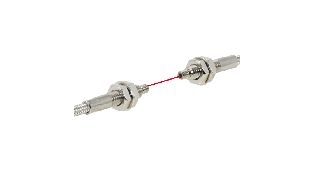
Specifications
| Part No. | 51690 |
|---|---|
| Model | NF-TH13 |
| Category | Heat resistant type |
| Type |
M4 Joint type |
| Detection method | Through-beam type |
| Optical axis direction | Straight view |
| Shape of fiber head |
M4 23 mm long |
| Sleeve | - |
| Optical axis diameter | ø1.0 mm |
| Fiber length |
Heat/Cold resistant side 0.3 m Ambient temperature fiber side 2 m |
| Free-cut | Possible only in the ambient temperature fiber |
| Min. bending radius |
Heat/Cold resistant side R18 Ambient temperature fiber side R25 |
| Degree of protection | RoHS directive (2011/65/EU) |
| Ambient temperature |
-60 ... +200°C 0 ... 40°C (at 85 % RH) |
| Ambient humidity | 35 ... 85 % RH |
| Applicable regulations | - |
| Weight | Approx. 45 g |
| Included items | Fiber cutter, M4 Hex nut x 6, Toothed washer x 2, M4 Hex nut (Plastic) x 2, Spring washer x 2 |
● The optical axis diameter is an approximate value.
Sensing Distance by Response Time
Unit: mm
| Fiber-Optic Sensor D4RF Series | Fiber-Optic Sensor D12R Series | ||
|---|---|---|---|
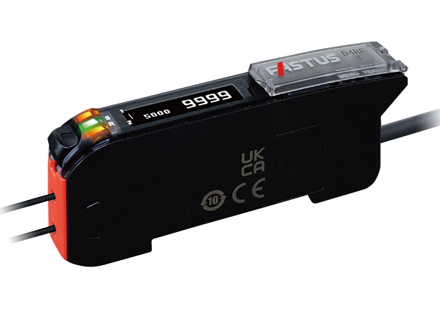
|
2,990 (8 ms) 2,065 (2 ms) 1,570 (1 ms) 1,330 (500 μs) 1,080 (250 μs) 680 (70 μs) 230 (16 μs/22 μs) |

|
2,360 (4 ms) 1,290 (1 ms) 900 (250 μs) 310 (50 μs) |
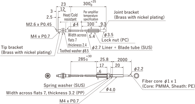
Dimensions
Unit: mm
Mounting Method
-
Connecting heat resistant joint fiber to ambient temperature fiber
- Use the following procedure to connect ambient temperature fiber.
Procedure
-
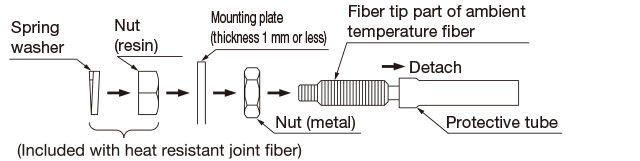
Attach the plastic nut included with the heat resistant joint fiber and spring washer as far as possible on the fiber tip of the ambient temperature fiber.

-
Mount the heat resistant joint fiber and ambient temperature fiber using a lock nut.

Note 1: Do not secure the lock nut using the plastic nut and spring washer from Procedure 1.
-
To prevent the lock nut from becoming loose, secure using the plastic nut used for mounting in Procedure 1.

-
If mounting connecting parts to the mounting plate
- If securing parts that connect the heat resistant joint fiber and ambient temperature fiber to the mounting plate using the included metal nuts, use the procedure below.
- The mounting plate thickness needs to be 1 mm or less.
Procedure
- Remove the protective tube from the ambient temperature fiber, attach the included metal nut from the tip of the fiber and move it to the fiber part.
- Insert the tip of the fiber into the mounting plate.
- Connect the heat resistant joint fiber to the ambient temperature fiber using the same procedure from <Connecting heat resistant joint fiber to ambient temperature fiber>
-
Tighten the metal nut mounted in Procedure 1 to the mounting plate.
<Operating Temperature>
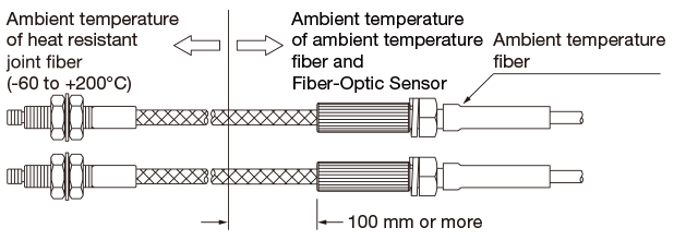
- In order to protect ambient temperature fiber and Fiber-Optic Sensor, keep the heat resistant joint fiber at least 100 mm from the boundary of the ambient temperature as shown in the diagram below.
Usage notes
-
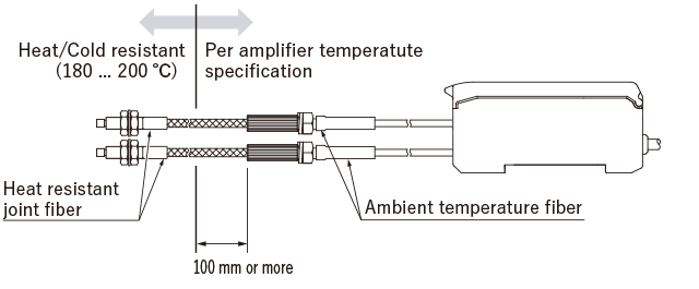
- In order to protect Fiber-Optic Sensor, keep the heat resistant fiber part at least 100 mm from the boundary of the ambient temperature as shown in the diagram below.
- Do not directly expose Fiber-Optic Sensor to radiation heat or hot air.
- The tip bracket of the heat resistant fiber (up to 350°C) and stainless steel sheath may change color when used at high temperatures, but this does not affect their detection capability.
Accessories
| Type | Part No. | Model | |
|---|---|---|---|
| Fiber cutter | 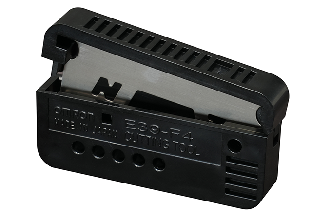 |
20228 | NFC-F01 |
Correct Use
Contact Us
Our experts quickly deliver the best plan for your needs and provide continuous support throughout the process.
Product Inquiry / Technical Support- Download List
- 20