

Correct Use
Measurement of Objects with Multiple Materials or Colors
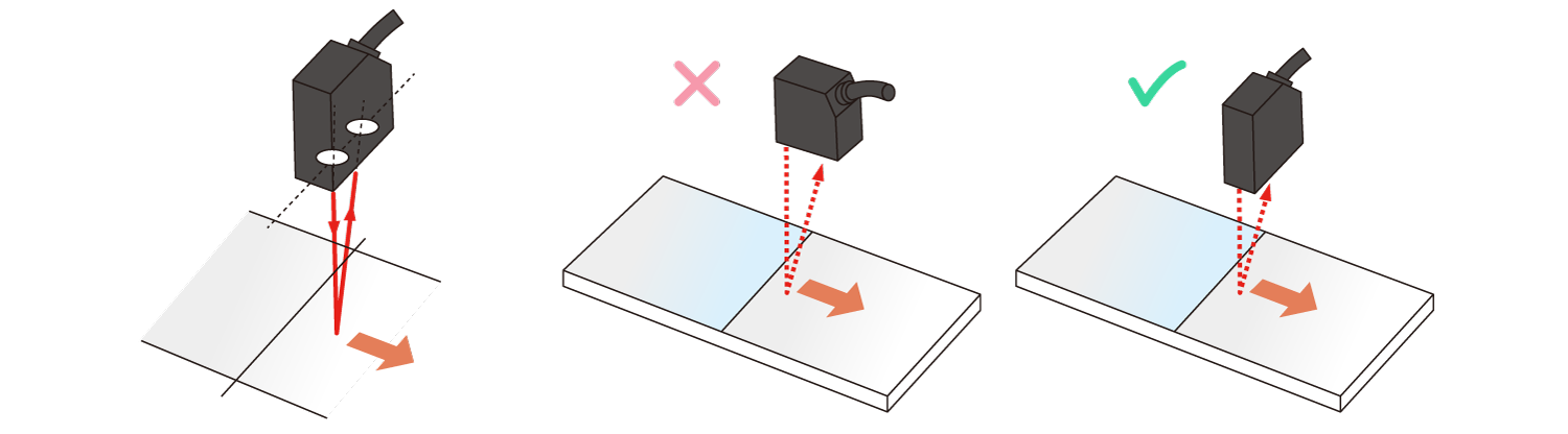
For measurement of objects with multiple materials or colors, install the face with emitter and receiver axis parallel to the border of materials or colors to reduce measurement errors, as shown on the drawings below.
Measurement of Narrow Grooves and Concaves
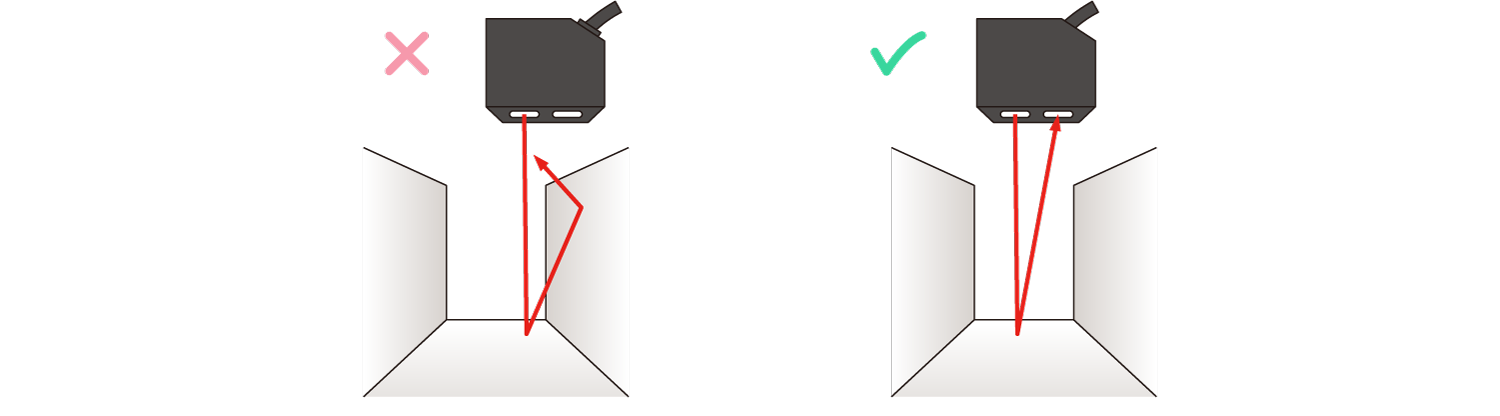
For measurement of narrow grooves and concaves surrounded by walls, install the emitter and receiver axes of sensor not to be blocked by the walls, as shown on the drawings below.
Measurement of Rotating Object
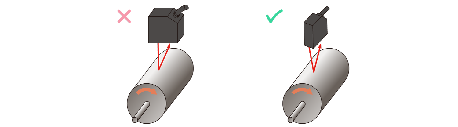
For measurement of rotating objects, installation of the line of emitter and receiver axes parallel to the rotation axis can minimize influence from variations of the object in vertical and horizontal directions.
Measurement of Objects with Height Gaps
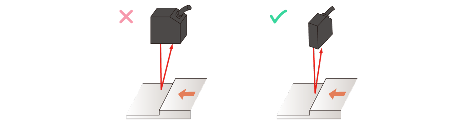
For measurement of objects with height gaps, installation of the line of emitter and receiver axes parallel to the edge of height gap can minimize influence from reflection by the edge.
Sensor Head and Nearby Wall
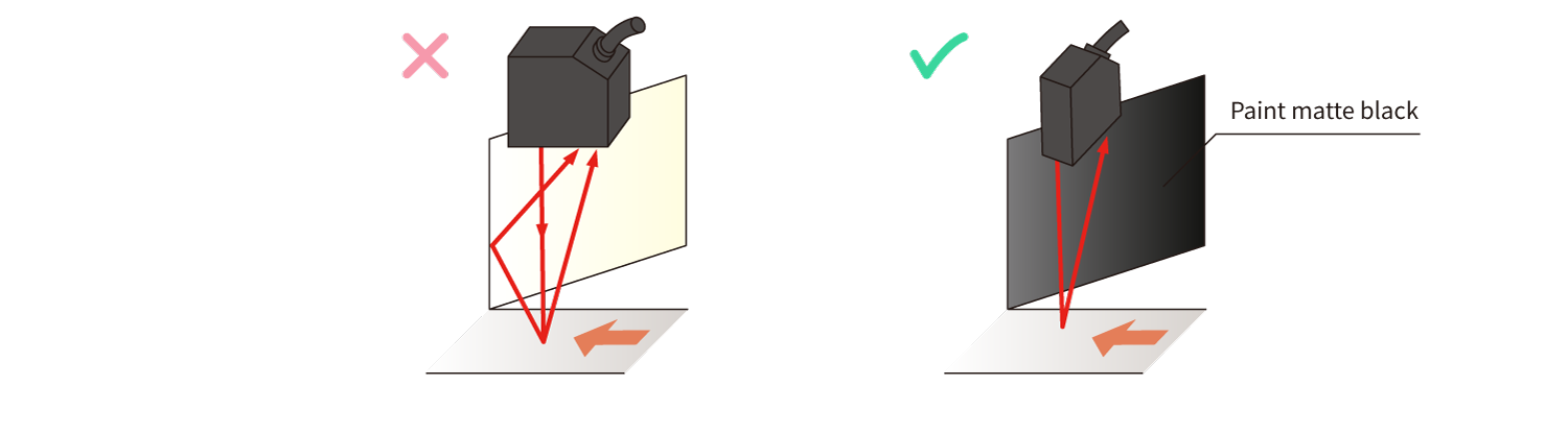
Receiving reflected light from a nearby wall can generate measurement errors. If installation away from the wall is impossible, install the line with emitter and receiver axes parallel to the wall, as shown on the drawing below. Painting the wall in matte black can reduce light reflection from the wall.
Measurement of Black Objects
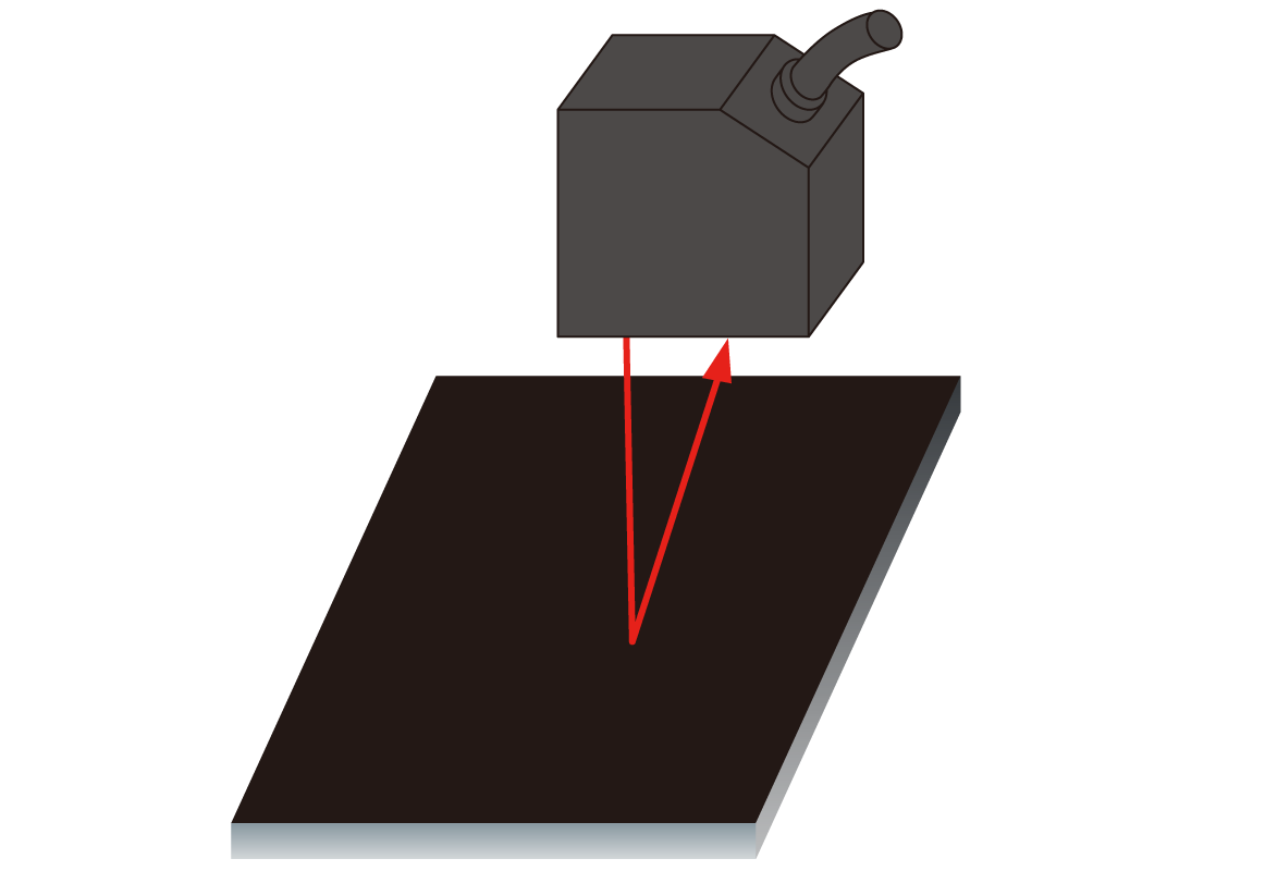
In case of black objects, reflected light amounts are small, then low values measured on the image sensor reduces the repeat accuracy.
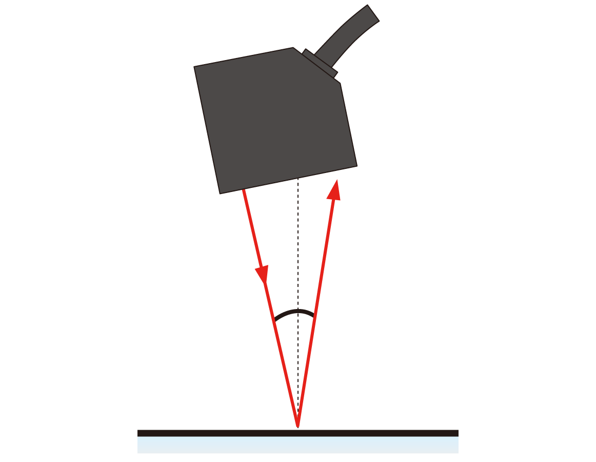
To increase light amounts reflected from the object, following installations are effective.
|
Installation in a Shorter Distance |
Installation at a Specular-reflection Angle |
|
|
|
- Download List
- 20