IO-Link Complete Guide

This section provides an easy-to-understand overview of IO-Link, its features and benefits. You can learn about IO-Link basic knowledge, technical explanations, and precautions from the tabs below.

1. What is IO-Link?

  • IO-Link is an industrial interface standard (IEC 61131-9) that connects sensors and actuators. This communication technology enables the exchange of various types of data, which have been managed manually one by one, at the sensor level in line with IIoT.
    IO-Link compatible sensors and actuators are called IO-Link devices, which are connected to various industrial networks such as EtherNet/IP, EtherCAT, PROFINET, Modbus TCP, CC-Link IE TSN, CC-Link IE Field and CC-Link IE Field Basic through the IO-Link Master.
    Sensors and actuators are connected to the IO-Link Master point-to-point, and are connected to controllers such as PLCs via industrial Ethernet.


Back to top 

2. IO-Link Features

Data Acquisition

In recent years, there has been an increasing need to digitize data from analog devices and incorporate it into systems. For this purpose, conventional devices are replaced with IO-Link devices. This is expected to reduce the number of devices such as A/D converters or lower the cost of devices.
Conventionally, at the sensor and actuator-level, ON/OFF signals, analog signals, and serial communications were wired separately. The IO-Link standardizes these processes, enabling more efficient operation.
At the same time, the following issues related to the use of analog I/O signals can also be solved.
- Change in measured values due to noise
- Convert errors during A/D or D/A conversion
- Scaling man-hours

Making machine and plant maintenance more efficient

Since the parameters once set can be backed up to the IO-Link Master, it is possible to avoid problems such as wrong model if the IO-Link device is replaced with one of the same model.
In addition, set-up information can be imported from IO-Link Master when replacing IO-Link devices, eliminating the need to fine-tuning.
The IO-Link Master can back up not only the profile of each IO-Link device, but also the setting information after various parameter adjustments.
If the IO-Link device is replaced with one of the same model, the setting information can be restored to avoid different information than before.

Back to top 

3. Components of IO-Link System and Their Roles

  • The IO-Link system mainly consists of IO-Link Master, IO-Link devices (such as sensors, actuators, etc.), cables and engineering tools.
    IO-Link Master is a terminal unit that performs IO-Link communication with an IO-Link device in an IO-Link system.
    IO-Link Master with multiple ports allows point to point bidirectional communication to IO-Link devices. The amount of communication data, response time are not affected by neighboring devices.
    IO-Link device is a generic term for sensor and actuator devices designed and manufactured based on the IO-Link standard.
    These include a wide variety of FA sensors, switches, RFIDs, and actuators.
    All devices have an IODD file that describes device information, which can be read to configure the device independently of the manufacturer.


Back to top 

4. Required Components for IO-Link

Back to top 

5. What you can do with IO-Link

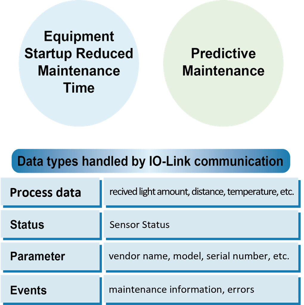
  • In a factory, there are thousands of sensors and actuators operating on production lines and equipment, and IO-Link makes it possible to monitor and setup information from many sensors and actuators that could not be centrally managed in the past, at the controller-level.
    The data that can be handled by IO-Link communication is shown on the left for a sensor.
    When changing lots or types, batch sensor settings and I/O checks can be performed from the PLC, and set-up information can be imported from IO-Link Master when replacing sensors. As a result, equipment start-up and maintenance time can be reduced.
    In recent years, there has been an increasing need for "preventive maintenance" to detect signs of equipment failure. Many IO-Link devices are pre-installed with these functions, making it possible to easily create "preventive maintenance" systems.


Number and type of IO-Link compatible devices

There are 16 million IO-Link compatible devices as of the end of 2019.
The number of nodes has approximately doubled in two years from 8.1 million at the end of 2017.
There is a wide range of IO-Link compatible devices.
Example: photoelectric sensors, displacement sensors, switches, RFID, actuators (driving devices), buzzers, indicator lights, etc.

Back to top 

6. Basic Data Types for IO-Link Communication

Process data (Cyclic Communication)

Data is communicated cyclically and can be obtained without a PLC program.
Process data size is determined by the device, with 0 to 32 bytes available. Ex.) Distance data for displacement sensor, temperature data for thermometers, flow data for flow sensor, etc.

Service data (Acyclic Communication)

This information includes parameters, identification data (model, serial number, etc.), and diagnostics.
These information can be communicated acyclic by request of the IO-Link Master.
Device data can be written to and read from the device.

Event data (Acyclic Communication)

If an error such as a short circuit, overheating, or contamination occurs or is predicted to occur in an IO-Link device, the master can be notified without interfering with process data transmission.
(Event details vary depending on the IO-Link device)
As for wire break between the IO-Link Master and the device, it can be detected if there is no response from the device after a retry from the master.

Back to top 

7. IO-Link Basic Terminology

IO-Link device Expansion devices such as sensors or actuators that can perform IO-Link communication with the IO-Link Master.
There are PLC unit type and remote network type that can be installed near sensors and actuators.
IO-Link Master Refers to a terminal unit that receives signals from an IO-Link device.
There are PLC unit type and remote network type that can be installed near sensors and actuators.
IODD file An IODD (IO Device Description) file contains information on device descriptions and parameter such as vendor name, model number, and functions of the IO-Link device.
IODDs are created by vendors that provide IO-Link devices, and many of them are available free of charge on their websites. IO-Link devices can be setup by reading IODD files from the IO-Link Master.
IO-Link mode This mode is for bidirectional digital communication of IO-Link data.
In IO-Link mode, process data and other data are communicated.
SIO mode (Standard IO) Conventional I/O (NPN, PNP) mode.
Used when connecting to devices that do not support IO-Link. (This is a unidirectional digital I/O signal.)
Process data Transmits data frames cyclically.
Size of the process data is determined by the device, with 0 to 32 bytes available.
Ex.) Distance data for displacement sensor, temperature data for thermometers, flow data for flow sensor, etc.
Status The process data value status.
Device data This information includes parameters, identification data (model, serial number, etc.), and diagnostics. These information can be communicated acyclic by request of the IO-Link Master.
Device data can be written to and read from the device.
Event If an error such as a short circuit, overheating, or contamination occurs or is predicted to occur in an IO-Link device, the master can be notified without interfering with process data transmission. (Event details vary depending on the IO-Link device)
As for wire break between the IO-Link Master and the device, it can be detected if there is no response from the device after a retry from the master.
IO-Link connection range Cable length between IO-Link Master and IO-Link device is Maximum 20 m.
IO-Link physical port M5, M8, and M12 circular connectors, clamp type, terminal block type, etc. are available.
Engineering tool Tool produced by various PLC manufacturers for PLC configuration.
Can be used for setting up IO-Link Master and device connected to PLC.
*Some items cannot be set.
A standard 3 to 5-wire unshielded cable The type of cable to be connected to the IO-Link sensor.
Port Class A (Type A) In general, it is compatible with 3-wire cable.
The function of pins 2 and 5 is not defined for this type.
Port Class B (Type B) In general, it is compatible with 5-wire cable.
Capable of connecting to high-capacity devices, this type has pins 2 and 5, which are primarily assigned to supply voltages.

Back to top