


Technical Guide for Displacement Sensors
1. What is Displacement Sensor
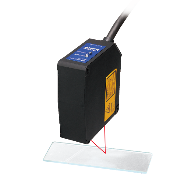
● Displacement sensors measure the height and thickness of workpieces and distances in units of micrometers.
● Photoelectric sensors detect the presence of workpieces, but displacement sensors can accurately measure a distance to object in micrometers.
-
* There are various types of displacement sensors including contact types, ultrasonic types, capacitive types, and inductive types. This technical guide explains laser displacement sensors, which are equipped with lasers as light sources of optical systems.
-
page top 
2. Main Features
-

- Non-contact measurement
-
-
- Long-distance measurement
-
- Small object measurement
-
- High-speed and high-accuracy measurement
-
- Measurable for most of objects
-

- Oil and dust on optical system
page top
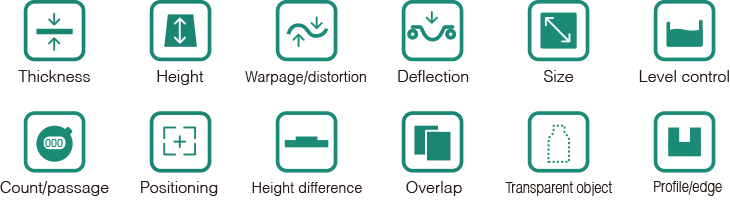
3. Measurements of Displacement Sensors
page top
4. Optical Systems of Displacement Sensors
-
Diffuse Reflective
The laser beam is emitted to a target object at right angle.
The receiver element detects reflected light from the object.
Measurement in a longer distance range can be made with this system.
This is not suitable for measurement against a transparent or specular object that rarely produces diffuse reflection.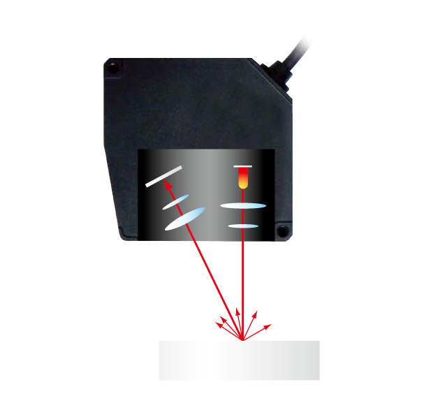
-
Specular Reflective
The optical system is installed at the same light axis angle of emittance and receipt, and mainly used for measurement of transparent and specular objects.
The measurement distance becomes shorter, however, higher measurement accuracy can be obtained.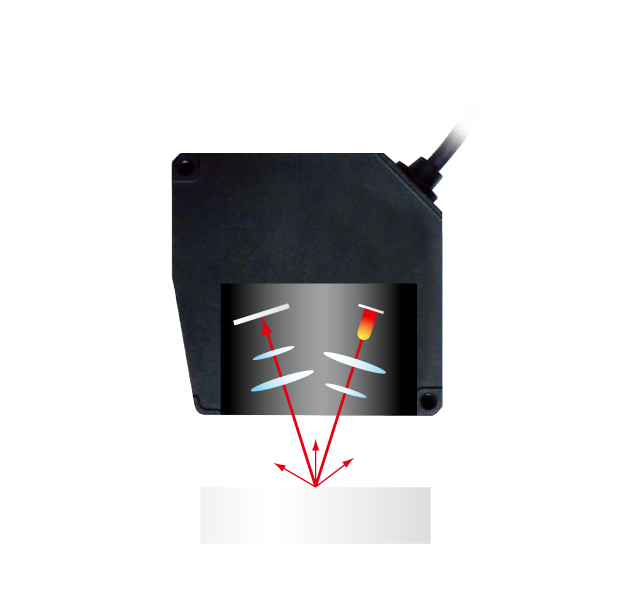
-
Through-beam
This sensor emits light of screen beam to measure blocked light width by an object.
The through-beam system avoids influence from color and surface conditions of an object and is suitable to measure a width, diameter and gap.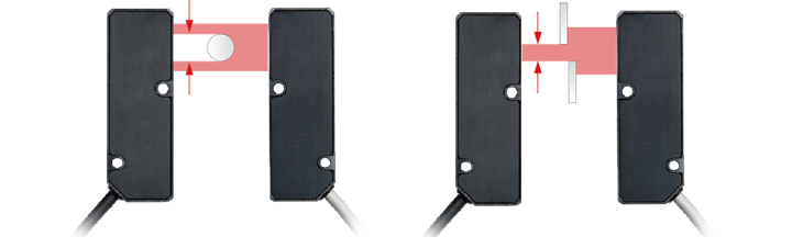
5. Product Line-up
The following are the line-up of displacement sensors for to meet requirements of accuracy, object and installation.
| CD22 Series | CD33 Series | CD5 Series | CDX Series | TD1 Series | |
|---|---|---|---|---|---|
| Optical System | Diffuse | Diffuse/Specular | Diffuse/Specular | Diffuse/Specular | Through-beam |
| Light Source | Laser Class 1 | Laser Class 2 CD33-L: Class 1 |
Laser Class 2 CD5-L: Class 1 CD5-W2000: Class 3R |
Laser Class 1 | Laser Class 1 |
| Light Receiving Element | C-MOS | ||||
| Structure | Built-in Amplifier | Separate amplifier | |||
| Linearity | ±0.1%F.S. | ±0.1〜±0.3%F.S. | ±0.05〜±0.1%F.S. | ±0.015〜±0.05%F.S. | ±0.4%F.S. |
| Sampling Period | 500~4000μs 4 modes |
500(750)~2000μs 4 modes |
100~3200μs 6 modes |
12.5~1000μs 7 modes |
500μs |
page top
6. Glossary
-
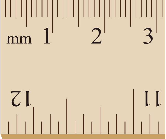
Resolution
This indicates how precise the measurement unit of sensor is. For example, The scale of this ruler is 1mm. so that its resolution is 1mm.
-
-
Repeat Accuracy
Even in a resting state, measurement values of a laser displacement sensor fluctuate.
The fluctuation of repeatedly measured values at a same point of object in a resting state is a repeat accuracy. -
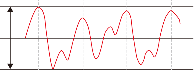
The repeat accuracy is a value between peaks and bottoms.
-
Full Scale (F.S.)
Model selection must be made, as a measurement distance, height difference and moving range between the sensor and object are within this range.

-
Linearity
Linearity is an error between a measured value and actual displacement, distance.
For displacement sensors, it describes a maximum difference in distance.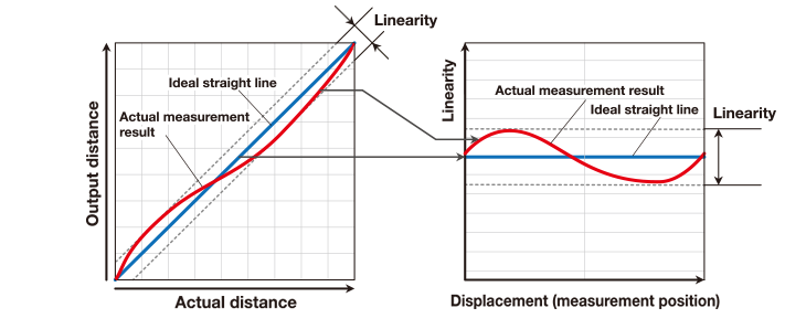
If a sensor has no error, an actual distance and measured distance make a straight line. This is an ideal line.
However, in reality, the actual measurement results shown in the graph have errors from the ideal line.
The variance calculated as a percentage of full scale is the linearity.
A distance value can be calculated by the following formula.
〈Calculating Formula〉
Linearity = +/- Percentage x Full Scale
〈Example〉
Linearity: +/-0.1%, Full Scale: +/-20mm
Linearity = +/-0.1% x +/-20mm
= +/-0.1% x 40mm
=+/-0.04mm, +/-40μm
-
Sampling Period/Sampling Frequency
Sampling period is time to take one measurement, and sampling frequency is the number of measurement per second, Hz.
To measure a low reflection object, such as a black rubber, the sampling period needs to be long to increase an amount of received light.
To measure a high reflection object, such as a polished metal, it is necessary to set the sampling period short to avoid the amount of received light saturated.
The displacement sensors of OPTEX FA are equipped with the AUTO function of sampling period that adjust to the best sampling period for measurement to minimize an error when the reflection rate changes.
-
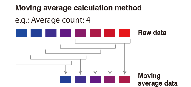
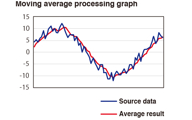
Averaging (Moving Average)
-
● Measured values of displacement sensor from multiple measurement fluctuate, even when an object is in a resting state.
The averaging is used to minimize the fluctuation.
The displacement sensors of OPTEX FA use the moving average to output an averaged measurement value upon every sampling. -
-
● Calculation of Moving Average
Example) Averaging: 4 samples
Measured value (raw data)
Measured value (average) -
-
Temperature Characteristics (Temperature Drift)
This is a characteristics of measured values that change along with change of operating temperature.
This is described as +/- 0.08%FS/Cº or 0.2mm/K, Kelvin.
In case of displacement sensor with +/-0.08%FS/Cº and 50+/-10mm range,
20mm, +/-10mm, x 0.0008 = 16μm
measured values fluctuate a maximum of 16μm per 1Cº.
-
Warm-up Time
This is time for a sensor to reach a performance level of its specifications, after turning power on.
(Time for internal temperature of sensor becomes stable.)
Typical time is 5 to 30 minutes, depending on a model.
-
Moving Resolution
Measured values of a moving object may fluctuate, even if a distance to the object has not been changed.
This occurs due to movement of a focal point on light receiving element, as the object moves.
This fluctuation of measured values to moved object is called moving resolution.
With an object with even surface, such as a glass or semiconductor wafer, fluctuation does not occur, but with most of other objects, it occurs.
Thus, when measurement is performed with an object moved, the moving resolution needs to be taken into consideration.
If laser points of spot and wide can be chosen, a model with wide beam minimizes influence by the moving resolution.
The moving resolution is not listed on a catalog, because it varies per a surface condition of object. The fluctuation needs to be confirmed upon actual testing.
page top