Technical Guide for Photoelectric Sensors
1. Main structure of photoelectric sensors
-
Important components in the structure of photoelectric sensors are a light source of emitter and light receiving element of receiver. In general, a LED and laser diode is used for light source and a photodiode or phototransistor is used for light receiver.
Wavelength
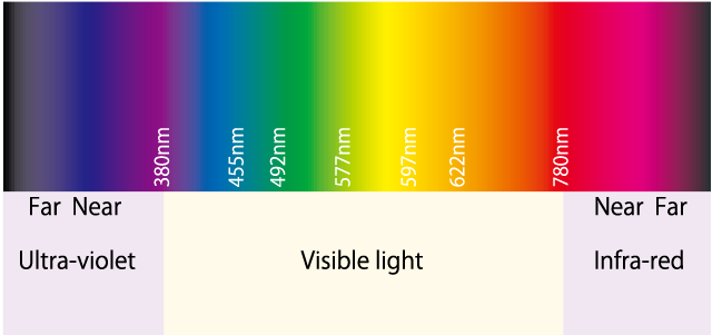
A color of light has a relationship with a wavelength of electromagnetic radiation.
The human eye can perceive the wavelength of light from about 400nm to 700nm.
The majority of photoelectric sensors operate within the wavelength of visible light. -
page top 
2. Characteristic charts
| Excess gain |
This is a ratio of a received light energy level to threshold of sensor amplifier. A figure represents a margin of sensor compared with level 1 as a standard specification. 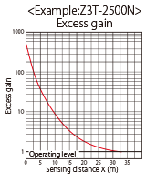
|
Interference area |
This is a distance between sensors next each other that a light from sensor does not interfere operation of another sensor. The chart shows a distance required between the sensors to detection distances on the X axis. 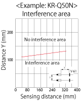
|
| Parallel deviation |
This describes how wide light is emitted from a through-beam or retro reflective sensor, when its sensitivity is adjusted at a Max. A horizontal distance from light axis to install a sensor can be found. 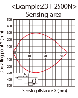
|
Angular deviation |
This shows installation angles between an emitter and receiver of through-beam sensor or a sensor unit and reflector of retro reflective sensor. Angles between sensor units or sensor and reflector to detection distances are shown on the chart. 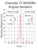
|
| Sensing area |
This shows detection areas in the horizontal direction of a diffuse reflective sensor. A detection point of object in the horizontal distance at a detection distance on the X axis can be found. 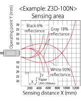
|
Hysteresis |
This shows detectable distance gaps to objects with different colors of a diffuse reflective sensor. Detectable gaps can be found for object colors and detection distances. 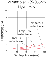
|
| Spot sizes |
This describes spot sizes of emitted light from a sensor. Spot sizes are shown to detection distances on the X axis. 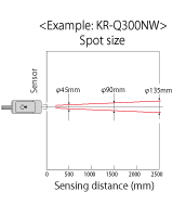
|
Material correlation |
This shows how much influence a BGS sensor have on detection from different materials of objects. Deviations of materials compared with a white paper at detection distances on the Y axis to detection performance can be found. 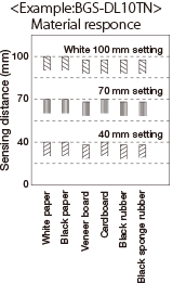
|
| Color correlation |
This shows how much influence a BGS sensor have on detection from different colors of objects. Deviations of material color compared with a white object at detection distances on the Y axis to detection performance can be found. 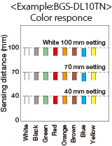
|
page top 
3. Standards and testing
-
Protective structure (IP: International Protection)
The protective structure is stated with the degree of protection defined by IEC, International Electrotechnical Commission, Japan Industrial Standards and Japan Electrical Manufacturers' Association Standards.
This can be referred to know environmental protection of sensors.
-
Rating Description 5 
Water projected by a nozzle against enclosure from any direction shall have no harmful effects. 6 
Water projected in powerful jets against the enclosure from any direction shall have no harmful effects. 7 
Ingress of water in harmful quantity shall not be possible when the enclosure is immersed in water under defined conditions of pressure and time. 8 
The equipment is suitable for continuous immersion in water under conditions which shall be specified by the manufacturer. -
Rating Description 5 
Ingress of dust is not entirely prevented, but it must not enter in sufficient quantity to interfere with the satisfactory operation of the equipment. 6 
No ingress of dust; complete protection against contact.

IP69K
-
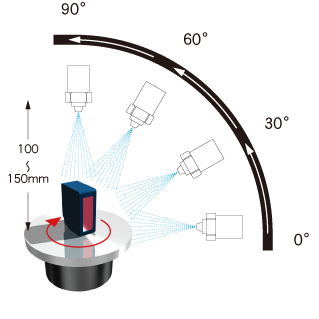
IP69K rating is defined in DIN 40050-9 of Germany extended the IEC 60529 rating system for high-pressure, high-temperature wash-down applications.
Enclosures must not only be dust-tight, IP6X, but are also able to withstand high-pressure and steam cleaning.
-
-
Testing conditions
Water is sprayed with the following conditions to a test device sits on a turntable that rotates at 5rpm.
Water pressure:80~100bar
Flow rate:14~16L/m
Water temperature:+80℃ / −5℃
Distance from nozzle:100~150mm
Spray angle:0°, 30°, 60°, 90°
Spray time:30s each angle
* The IP69K rating does not guarantee operation of a rated product under all of the above conditions.
Water or oil on the optical surface could cause light refraction to interfere correct detection.
Feilen noise testing (Referential data)
-
The products are tested against noise influence at specific frequencies with noise simulators specified in IEC standards.
However, there is no easy-to-understand indicator against noise in actual production floors, such as motor noise, welding noise, etc.
Therefore, the following testing is made at OPTEX FA.Feilen noise testing (File testing)
A device performance test against noises from various sources, such as a motor, inverter lamp, welding, electric arc, etc.
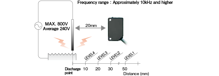
Testing method
Noise levels are defined at distances from a device and spark generated by metal filing.
Product Series Feilen noise level Product Series Feilen noise level D3RF, D3IF LEVEL4 TOF-DL LEVEL3 Z3 LEVEL3 TOF-L LEVEL3 Z-M, BGS-ZM LEVEL3 DR-Q LEVEL3 E LEVEL3 KR-Q LEVEL4 V2, BGS-2V LEVEL3 DM-18T LEVEL4 V3, V4 LEVEL3 CDX LEVEL4 Z-L, BGS-ZL LEVEL3 CD22 LEVEL3 DS LEVEL3 CD5 LEVEL4 BGS-HL LEVEL4 CD33 LEVEL4 BGS-HDL LEVEL4 TD1 LEVEL3 BGS-DL10T/-DL25T LEVEL3 LS LEVEL3 BGS-Z, ZR-QX LEVEL3 * Please contact us about noise resistance of other products not listed above.
Shock testing (Referential data with KR-Q Series)
-
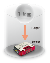
Passed for drop testing from 1.4m height!!
(The sensor is not damaged, even when it is hit with a sharp edge.)
-
Testing method
A weight of 1kg is dropped to a product from the top.
The weight is guided through a pipe to apply the shock evenly on a side of sensor.
The height to drop the weight is raised by 10mm, and at each height, operations of the sensor are tested.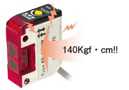
Environmental protection (Noise resistance)
-


IEC 61000-4-2:2008, Electrostatic discharge immunity
Device performance against electrostatic discharge is tested.
A product shall not be damaged at the following levels of electromagnetic wave.Air discharge 2kv Level 1 4kv Level 2 6kv Level 3 8kv Level 4 Contact discharge 2kv Level 1 4kv Level 2 8kv Level 3 15kv Level 4 Resistance against ambient illuminance
Performance against ambient illuminance with light reflection at 30~45 degrees into a direction of light axis is tested.
A product shall not be malfunctioned with the following light reflection.Sunlight 10,000lx Fluorescent lamp 3,000lx High-frequency fluorescent lamp 3,000lx Xenon flash lamp 3,000lx 

IEC 61000-4-3, Electromagnetic field immunity
Resistance against radio wave of 80MHz ~ 1GHz is tested.
A product shall not be malfunctioned under the following levels.magnitude of electric field 1V/m Level 1 3V/m Level 2 10,000lx Level 3 Resistance against vibration
A product is tested for correct functions after vibration test of 10~55Hz, 1.5mm amplitude for 2 hours each in X, Y and Z directions.

IEC61000-4-4, Electrical fast transient/burst immunity test
Resistance against the immunity of electrical and electronic equipment to repetitive electrical fast transients, such as On/Off of relay, start up of motor, On/Off of switch, etc. is tested.Power supply terminal Input/output terminal Level 0.5 kV 0.25 kV 1 1 kV 0.5 kV 2 2 kV 1 kV 3 4 kV 2.0 kV 4 IEC 60068-2-27, Shock
A device is tested, after shock of 500m/s2, 50G is applied 3 times in each direction of X, Y and Z.
IEC 60529, Degrees of protection provided by enclosures
A product is tested for protection against solid particle and liquid ingress.
A product shall not be malfunctioned under the following conditions.Solid particle …… Any solid particle does not enter inside of a device. Liquid ingress …… Ingress of water in harmful quantity shall not be possible, when a product is immersed in 1 meter of water for 30 minutes
International safety standards
-
 CE Marking
CE marking is an administrative marking of its conformity with European health, safety, and environmental protection standards for products sold within the European Economic Area.
[Examples of applicable standards in European countries]
EMC directive 2014/30/EU: EN 61000-6-2, EN 61000-6-4
EN 60947-5-2, EN 60947-5-7
EN 55011, EN 61326-1, EN 61131-2
Low Voltage Directive 2014/35/EU
IEC 60947-5-2, IEC 61010-1 -

 UL Standards (USA and Canada)
Applicable products of OPTEX FA are certified for a listed product or recognized component as categorized in UL Standards for Electrical and Electronic Products.
-
 CCC, China Compulsory Certificate
The China Compulsory Certificate mark, CCC Mark, is a compulsory safety mark for mandatory products both Chinese-manufactured and foreign-imported that are sold or used in the Chinese market.
The CCC mark is administered by the CNCA, Certification and Accreditation Administration of the People's Republic of China.
page top 
4. Safety Standards Conformance List
| Purpose and condition | Category 2 | Series | CE | UL | CCC*1 | China RoHS |
|---|---|---|---|---|---|---|
| Fiber Sensor | Fiber-Optic Sensors | BRF | 〇 | - | N/A | 〇 |
| D1RF | 〇 | 〇 | N/A | 〇 | ||
| D2RF | 〇 | - | N/A | 〇 | ||
| D3RF/D3IF | 〇 | - | N/A | 〇 | ||
| V2RF | 〇 | 〇 | N/A | 〇 | ||
| Communication Unit | UC1-CL11 | 〇 | 〇 | N/A | 〇 | |
| UC1-EC | 〇 | 〇 | N/A | 〇 | ||
| UC1-EP | 〇 | 〇 | N/A | 〇 | ||
| UC2-IOL | 〇 | 〇 | N/A | 〇 | ||
| Photoelectric Sensor | Laser Sensor | DS | 〇 | 〇 | N/A | 〇 |
| Z-L | 〇 | 〇 | N/A | 〇 | ||
| LED Sensor | C2 | 〇 | 〇 | N/A | 〇 | |
| C-R | 〇 | - | N/A | 〇 | ||
| E | 〇 | - | N/A | 〇 | ||
| J | 〇 | - | N/A | 〇 | ||
| S | 〇 | 〇 | N/A | 〇 | ||
| V | 〇 | 〇 | 〇 | 〇 | ||
| V2 | 〇 | 〇 | N/A | 〇 | ||
| V3/V4 | 〇 | 〇 | N/A | 〇 | ||
| ZR-X | 〇 | 〇 | N/A | 〇 | ||
| Z-M | 〇 | 〇 | N/A | 〇 | ||
| Z2 | 〇 | - | N/A | 〇 | ||
| Z3 | 〇 | 〇 | N/A | 〇 | ||
| Z4 | 〇 | 〇 | N/A | 〇 | ||
| Distance Setting Sensor | LED Sensor | BGS-2V | 〇 | 〇 | 〇 | 〇 |
| BGS-C | 〇 | 〇 | N/A | 〇 | ||
| BGS-S | 〇 | 〇 | N/A | 〇 | ||
| BGS-Z | 〇 | - | N/A | 〇 | ||
| BGS-ZM | 〇 | 〇 | N/A | 〇 | ||
| BGS | 〇 | 〇 | N/A | 〇 | ||
| Laser Sensor | BGS-DL | 〇 | 〇 | N/A | 〇 | |
| BGS-HL | 〇 | 〇 | N/A | 〇 | ||
| BGS-HDL | 〇 | - | N/A | 〇 | ||
| BGS-ZL | 〇 | - | N/A | 〇 | ||
| TOF-DL | 〇 | 〇 | N/A | 〇 | ||
| TOF-L | 〇 | 〇 | N/A | 〇 | ||
| TOF-3V | 〇 | 〇 | N/A | 〇 | ||
| Transparent-object Detection Sensor | Laser Sensor | DR-Q | 〇 | 〇 | N/A | 〇 |
| LED Sensor | KR-Q | 〇 | - | N/A | 〇 | |
| SR-Q | 〇 | 〇 | N/A | 〇 | ||
| Z3R-Q | 〇 | 〇 | N/A | 〇 | ||
| ZR-QX | 〇 | 〇 | N/A | 〇 | ||
| Color Mark Sensor | RGB LED | DM | 〇 | 〇 | N/A | 〇 |
| Fiber-Optic Sensors | D3WF | 〇 | 〇 | N/A | 〇 | |
| Displacement Sensor | Beam Sensor | CD22 | 〇 | 〇 | N/A | 〇 |
| CD33 | 〇 | 〇 | N/A | 〇 | ||
| CD5 | 〇 | 〇 | N/A | 〇 | ||
| CDX | 〇 | 〇 | N/A | 〇 | ||
| Amplifier | CDA | 〇 | 〇 | N/A | 〇 | |
| 2D Sensor | LS | 〇 | 〇 | N/A | 〇 | |
| Edge Sensor | TD1 | 〇 | 〇 | N/A | 〇 | |
| Communication Unit | UQ1-01 | 〇 | - | N/A | 〇 | |
| UQ1-02 | 〇 | - | N/A | 〇 | ||
| Vision Sensor | All-in-one | CVS1-RA | 〇 | - | N/A | 〇 |
| CVS2-RA | 〇 | - | N/A | 〇 | ||
| CVS3-RA | 〇 | - | N/A | 〇 | ||
| CVS4-RA | 〇 | - | N/A | 〇 | ||
| CVSE1-RA | 〇 | - | N/A | 〇 | ||
| Multi-camera | MVS-EM-R | 〇 | - | N/A | 〇 | |
| MVS-OCR2 | 〇 | - | N/A | 〇 | ||
| MVS-PM-R | 〇 | - | N/A | 〇 | ||
| Thermometer | Installation | BA | 〇 | - | N/A | 〇 |
| BS | 〇 | - | N/A | 〇 | ||
| CS | 〇 | - | N/A | 〇 | ||
| SA-80 | 〇 | - | N/A | 〇 | ||
| Hand-held | PT-2LD | 〇 | - | N/A | 〇 | |
| PT-5LD | 〇 | - | N/A | 〇 | ||
| PT-7LD | 〇 | - | N/A | 〇 | ||
| PT-S80/-U80 | 〇 | - | N/A | 〇 |
*1 N/A, not applicable.
* Please contact OPTEX FA sales for details, such as applicable model numbers.
page top 


