LED Lighting Technical Guide
- 1. LED lighting
- 2. Feature of LED lighting
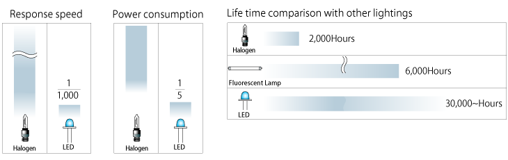
- 3. Comparison chart of LED lighting and others
- 4. FALUX sensing LED lighting of OPTEX FA
- 5. LED emission spectral distribution
- 6. Light scattering rate
- 7. Spectral luminous efficiency
- 8. LED lighting selection guide
- 9. Tips on aligning lighting, camera and target object
- 10. Points to select lighting
- 11. The Visual Field of Coaxial Lighting
- 12. Controllers/Power supplies selection guide
- 13. PWM dimming controller
- 14. Emission spectrum diagram
1. LED lighting
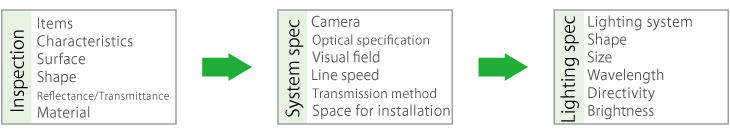
Important factors for LED lighting for machine vision
-
1) Shape and color
By lighting with adequate shape and color, clear and sharp image with high SN ratio can be captured that will help high quality image processing.
-
2) High surface uniformity
To get even reflection from the object surface, surface uniformity is very important.
-
3) Stable lighting
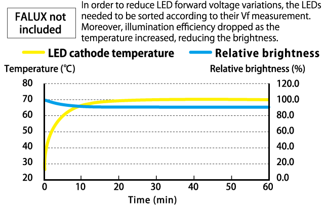
Brightness of LED lighting can be changed by ambient temperature of the LED lighting and also by deterioration of itself.
By stabilizing brightness in the period of the LED lighting life, maintenance can be minimized.
2. Feature of LED lighting

3. Comparison chart of LED lighting and others
<- Better ◎ - ◯ - △ - ☓ Worse ->
|
Light source |
Life | Brightness |
Wavelength selection |
Shape flexibility | Evenness | Directivity | Cost efficiency |
Switching performance |
Power consump tion |
|---|---|---|---|---|---|---|---|---|---|
| LED | ◎ | ◯ | ◎ | ◎ | ◎ | ◎ | ◯ | ◎ | ◎ |
| Halogen | ☓ | ◎ | △ | △ | △ | △ | ◯ | △ | ☓ |
|
FluL oaremscpent |
△ | ◯ | ☓ | ☓ | ◎ | △ | ◎ | △ | ◯ |
| Xenon | ☓ | ◎ | △ | △ | △ | △ | ◯ | ◎ | ☓ |
The reason the LED light is selected as a light source for machine vision is because it facilitates optimal lighting for inspection.
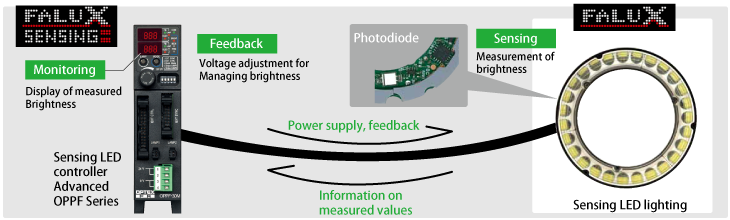
4. FALUX sensing LED lighting of OPTEX FA
Problems with conventional LED lighting:Three problems arise in managing brightness
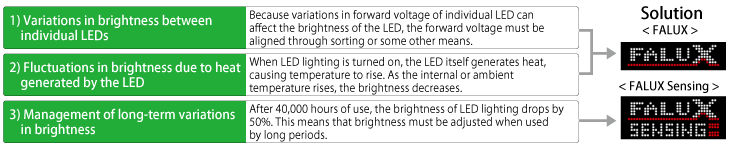
FALUX sensing LED lighting and controller
Brightness of LED lighting equipped with "FALUX sensing" can be controlled by controller equipped "FALUX sensing" feature by monitoring and feedback functions automatically.
"FALUX" brightness variation correction(Patent registered)

Using the constant current circuit dependent on the input voltage, variations in the forward current of individual LEDs are corrected for uniform brightness. Meanwhile, the temperature compensation circuit compensates for fluctuations in brightness due to increases in temperature after lighting or changes in the ambient temperature.

"FALUX sensing" for monitoring brightness and temperature and also feedback control of brightness(Patent registered)

-
LED brightness sensing is performed using multiple built-in photodiodes. This allows for accurate measurement of LED brightness not only during continuous illumination but also with short period illumination. Absolute brightness is stored in the lighting's internal memory to allow for instrumental error adjustment.
"FALUX sensing" also makes it possible to measure both the LED brightness of lighting and the internal temperature, and then to monitor those measurements on the power supply side.
Based on the monitored values, feedback control can be performed from the OPPF Series controller, making it possible to maintain the factory default brightness for around-40,000 hors. -

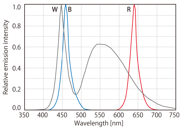
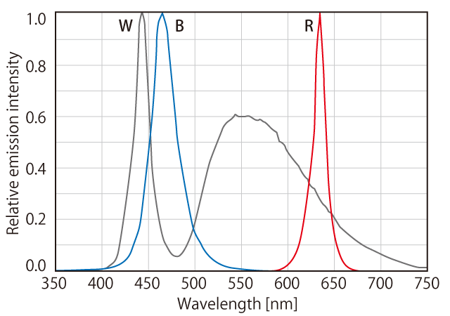
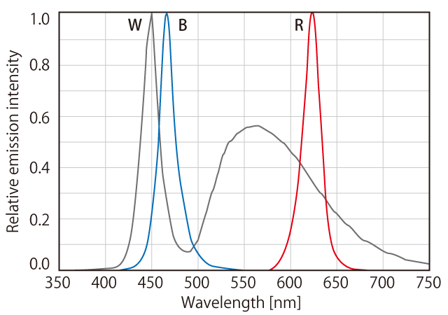
5. LED emission spectral distribution
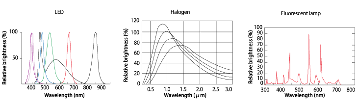
Fluorescent lamp and Halogen have wide wavelength distribution, but LED lightings have specific emission of light wavelength in each. When selecting LED lighting, please consider the feature of each wavelength.
6. Light scattering rate
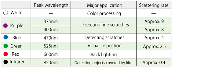
Following chart shows relative scattering rate presuming scattering rate of red light as "1". The shorter wavelength, the bigger scattering rate. This means that the short wavelength light can be reflected by small and narrow scratches more than longer wavelength light. Although, image sensor has small sensitivity for shorter wavelength light than green light. Infrared light can be used for inspection of object covered by film for example.
7. Spectral luminous efficiency
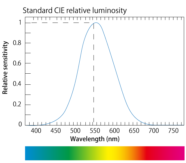
Visible light can be seen by human eyes. Visible light generally has a wavelength of between 380nm and 780nm.
Light with a wavelength longer than 780nm is infrared and light with a wavelength shorter than 380nm is ultraviolet. The human eye is most sensitive to green light with a wavelength of 555nm. Sensitivity decreases if the wavelength increases or decreases. The relative sensitivity curve when strength at 555nm is set as 1 is called "Standard CIE Relative Luminosity". Measurements of brightness such as lux and cd/m2 are coefficients of this Spectral Luminous Efficiency. The spectral sensitivity of a camera does not necessarily have the same distribution.
The sensitivity of some cameras is set to match infrared or ultraviolet ranges. When setting Lighting, please check athat the light distribution matches the features of camera you are using.

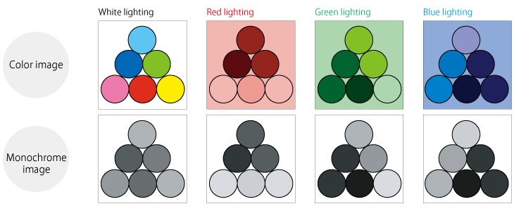
8. LED lighting selection guide

By combining the light of red, green and blue, you can create other colors. Green(G) and blue(B) make Cyan(C), B and red(R) make Magenta(M), and R and G make yellow(Y). By combining R, G, and B lights of the same strength, white(W) is created. Combining colors in this way is called additive color mixing and RGB are called Additive primary colors.
Colors can also be created by absorbing parts of light. C absorbs R, M absorbs G, and Y absorbs B. C, M, and Y absorb all of the light, and black(K) is created. Combining colors in this way is called subtractive color mixing and CMY are called Subtractive primary colors.
Following patterns show how the images change by color of lighting. In case of machine vision, most important point is the contrast between target part of the object and other part. The higher contrast, the better result the system will provide. Please refer following patterns when selecting lightings.
9. Tips on aligning lighting, camera and target object
Reflection of light varies by the object materials.
Please refer following examples
-
Specular reflection
(bright field)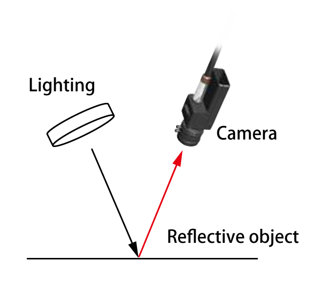
Reflected light is captured by the camera. Evenness of the light is required for capturing clear image rather than brightness. Irregularities on the surface and areas of low reflectance will be dark comparatively.
-
Diffuse reflection
(dark field)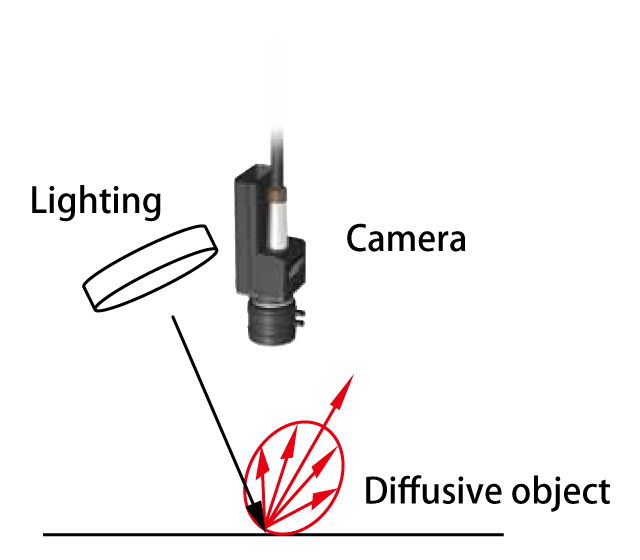
The camera captures a part of scattered light reflected off the surface. Light is reflected in every direction so the camera alignment is not so restricted. Since only a part of the light can be captured, brightness rather than evenness is required.
Irregularities on the surface and areas of high reflectance will be bright comparatively. -
Specular transmission
(bright field)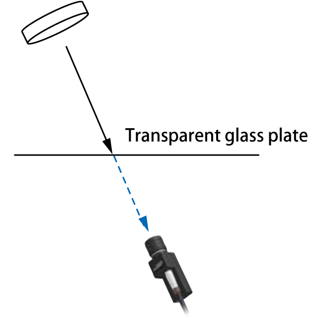
The camera is looking the lighting through the glass plate and the light goes through the glass plate is captured. Evenness rather than brightness is required in this case.
Irregularities on the surface and areas of low reflectance are comparatively dark. -
Diffusive transmission
(dark field)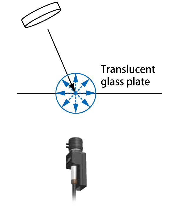
The camera captures a part of diffused light goes through the glass plate. Light diffuses to every direction so the camera's observation axis is not restricted.
Since only a part of the light can be captured, brightness rather than evenness is required.
Irregularities on the surface and areas of high reflectance are comparatively bright.
10. Points to select lighting
When selecting the Lighting it is necessary to consider several factors. Even when using the same Lighting, if the height of the lighting is different the captured image will be completely different. Also, if the Lighting wavelength (color) is different, the images change. Please consider the points below:
How to utilize LED lightings getting the best performance
1) Don't use in high temperature atmosphere not to accelerate deterioration
When the LED element get heated, luminance is reduced and general performance deteriorates. The half-life of the luminance of an LED element is said to be around 40,000 hours (Typ.), but if the element is continuously used in a high-temperature environment, its performance may deteriorate quicker.
2) How to prevent high temperature
•Improve the heat dissipation of the LED lighting
Mount the Lighting on a bracket with good heat conductivity.
•Turn the Lighting only when capturing image
The performance of LED Lighting is not affected much by switchin g. To extend the LED life, utilize the switching by external power supply.
•Lower the brightness of the lighting as much as possible
The lower the brightness, the smaller current flow to the LED an d heat generation is also smaller.
Open camera's aperture as much as possible to reduce LED curren t.
3) Mount the LED lighting as close as possible to the object
The closer the distance between LED lighting and the object, the brighter image the camera can capture.
11. The Visual Field of Coaxial Lighting
-
Coaxial Lighting is a type of Lighting in which the surface emitting part of the LED emits light along the same axis as the camera lens, via a half-mirror. The effective visual field of coaxial lighting is dependent upon the distance between the camera and object (WD), the distance between the Lighting and object (LWD), and the size of the light emitting surface.
If the WD increases, the visual field grows, but if the LWD increases, the visual field shrinks.
The method of calculating the effective visual field is shown at right hand side. It is necessary to keep the object within the effective visual field, especially for objects with a high reflectance. This effective visual field is calculated based on the size of the light emitting surface. It is recommended that you set a sufficient visual field, taking into consideration preventing lower luminance at the surrounding area. -

12. Controllers/Power supplies selection guide
| Series |
Output for lighting |
Dimming control | Channel |
Capacity (W) |
Illumination control input |
Input voltage |
|
|---|---|---|---|---|---|---|---|
OPPF
|
PWM: DC12V |
Digital 1,000 steps |
100kHz/ 500kHz PWM |
2 |
30, 48 |
10bit Parallel, RS232, Analog 0-5V |
DC24V |
|
Strobe: DC18V (1ms Max.) |
Digital 1,000 steps Strobe out: 10µs~999ms |
||||||
| OPPD-15 | DC12V |
Digital 1,000 steps |
100kHz/ 500kHz/ 1MHz PWM |
1 | 15 | No | |
|
OPPD-30E
|
100kHz PWM |
2 | 30 | Ethernet | |||
| OPPCW |
PWM: DC12V |
Digital 256 steps |
78.125kHz PWM |
2 | 26.4 |
8bit Parallel, Analog 0-5V |
AC100 ~240V |
|
Constant current: 700mA |
Max. current 7 level range switching, 256 steps |
Constant current |
|||||
*All controllers/power supplies above can control LED lightings.
Note: When using in conjunction with other equipment, the characteristics of the other equipment will affect the power supply, so be sure to choose a power supply that has a sufficient margin (around twice).
13. PWM dimming controller
PWM (Pulse Width Modulation) dimming changes pulse width to control brightness of LED lightings.
Various PWM frequencies are available from 50kHz up to 1MHz.

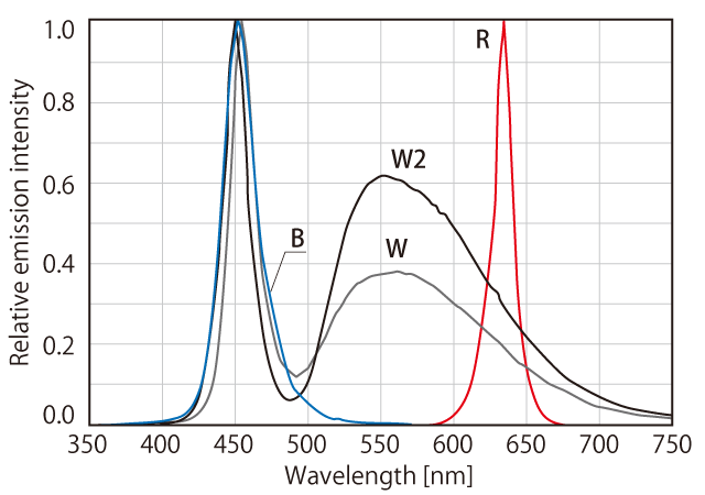
14. Emission spectrum diagram
The lamp emission spectrum distributions for each LED lighting series are displayed here.
The horizontal axis is the wavelength (nm), and the vertical axis is the relative emission intensity.
Data is for reference purposes.
Please note that actual products will vary slightly.
-
OPR/OPR-SF
-
OPB/OPB-S
-
OPF/OPX
-
OPS-S