


2-dimensional Laser Displacement Sensors
LS Series
Line beam for fast, accurate measuring of height and width



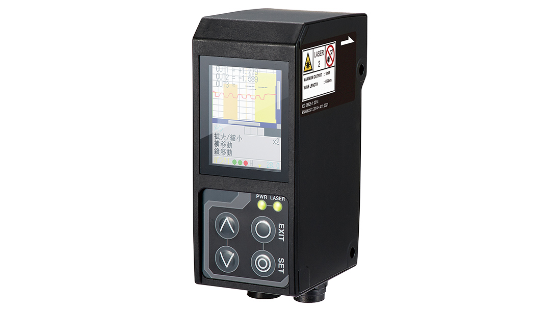
- Linearity of ±0.1% F.S.
- Sampling period of 0.5 ms (max. speed)
- 2-dimensional measurements at a significantly low cost
Line beam provides high-speed, high-precision measurement of height and width
These sensors can be used on any manufacturing line to perform the shape measurements required for quality management of parts and materials. With the FASTUS LS Series, high-accuracy 2D measurement sensor achieved both super cost effectiveness and significantly high speed measurement that conventional 1D measurement sensors can't achieve.
These are next generation 2D displacement sensors that have created a whole new category in part measurement.
-
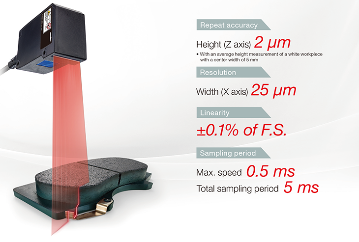
High speed, compact size and low price are achieved using OPTEX FA original method
Employing a mathematical operation known as a projection transformation, which converts a captured image into distance, allows both height and width to be measured with a high degree of precision. Also, by employing OPTEX FA original method in which projection transformations, normally performed on all pixels in the case of competitors’ products, are performed after triangulation, processing levels are significantly compressed, allowing high speed to be achieved. Furthermore, a more compact and low cost product has been realized by making processors smaller size.
-
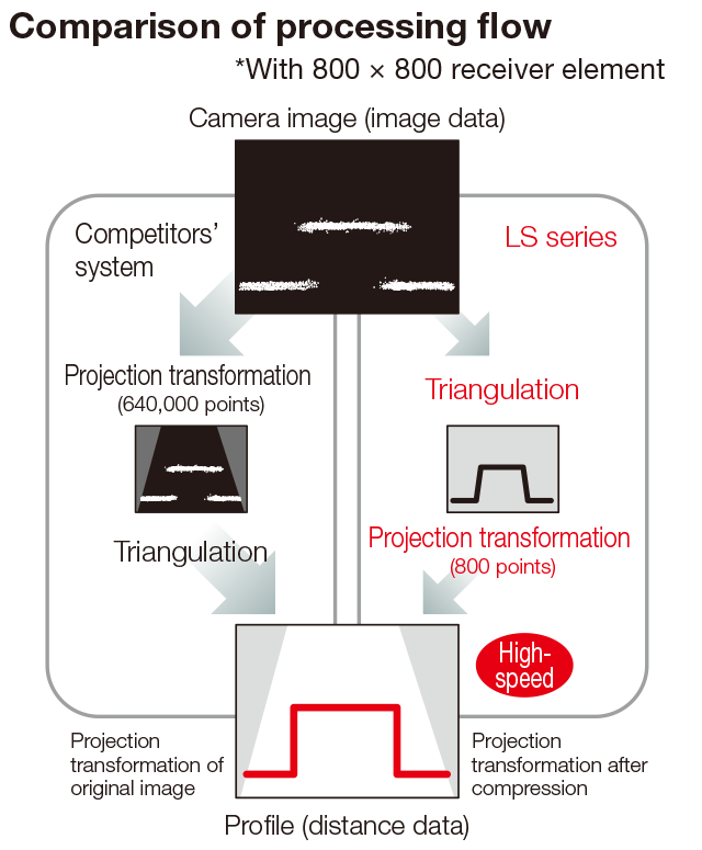
Easy Setup
The LS Series can be configured in four easy steps: camera imaging, area measurement and area calculation, and result judgment and output.
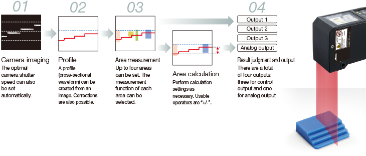
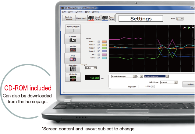
Easy setup PC software
LS-Navigator (included with delivery)
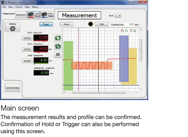
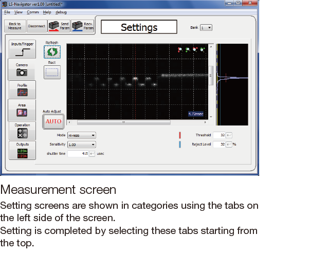
With delivery, the LS Series comes with software that lets you easily confi gure settings from a PC.
• Easy configuration of capturing area and measurement area settings
• All settings can be configured via RS-485 communication
• Profiles can also be output with high precision
• No need for expensive dedicated displays
*PC connector cable (optional) required separately.
Storage function
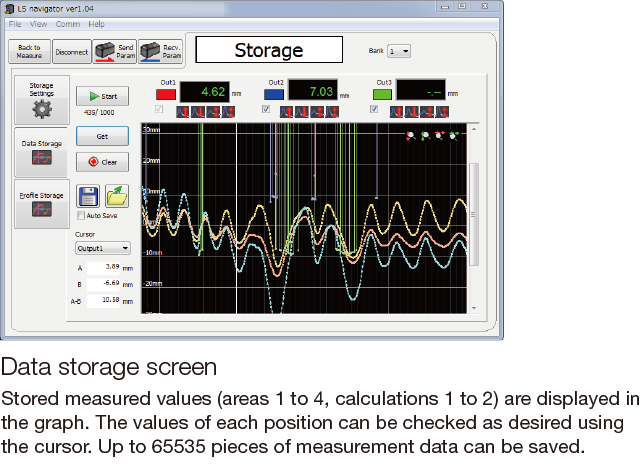
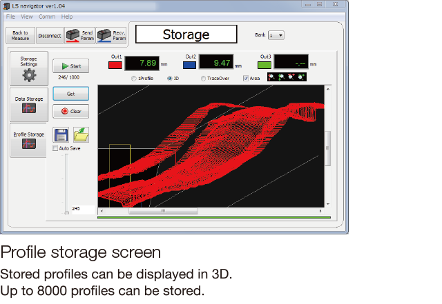
Measurement result and “Profile + Measurement result” can be stored and those data can be sent to PC through RS-485 communication. All the sampling data can be obtained regardless of the communication speed, and by using the LS-Navigator, it is possible to obtain data without the use of programs.
Because obtained data can be saved in CSV format, it can be accessed using spreadsheet software, etc.
Various measurement functions
-
Height
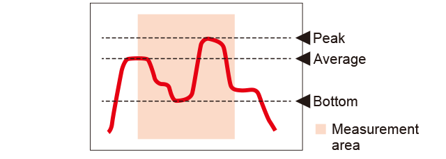
Average, peak, and bottom heights can be measured.
Average values, max. values, and min. values of a profile within an area are output. -
Position
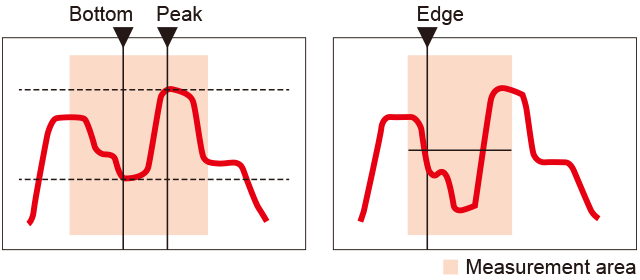
Peak, bottom, and edge positions can be measured.
-
Width

Groove and height difference widths can be measured. Profile widths are detected using the center position in the height direction of the area.
-
Edge count
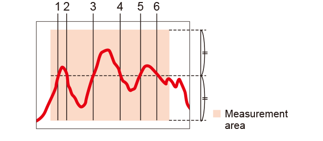
The number of times the center of the area's height is crossed is counted.
Use is also possible for pin counts, etc.
-
Tilt (°)
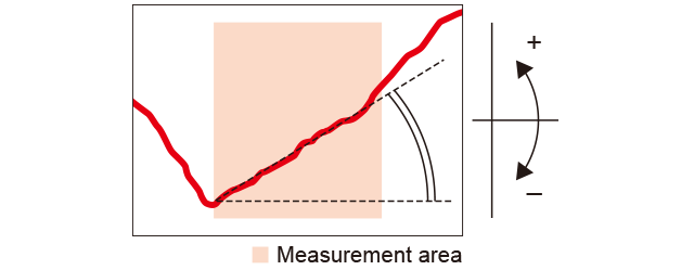
A straight line approximating the profile is created and its tilt is measured. (Unit: °) The angles of both sides of grooves and protrusions are measured and calculated.
-
Area (mm2)
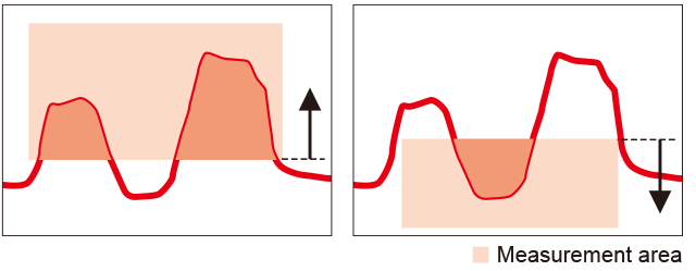
The area between an area and a profile is calculated
Measuring the “↑” portion reveals the cross-section of the protrusion, while the “↓” portion reveals the cross-section of the concave.
-
Line length

The profile length is measured. Because the same value will be achieved even if the position is changed, usage is possible without having to perform position corrections.
-
Diameter
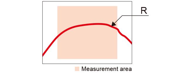
The diameter of the approximate bending line of the measured results is measured. This can be used for calculating the diameters cylinders, protrusions or grooves.
A wide-range of measurement variations using area calculations
-
▪ Example of height difference measurement
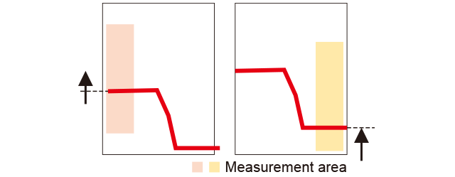
Height is measured at two areas (top and bottom surfaces) from which the height difference can be measured by subtracting. Small unevenness and variations can be ignored and it is possible to perform more stable measurements than with 1D displacement sensors.
-
▪ Example of angle measurement
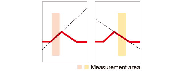
Tilting to the left or right is measured using two areas from which the angle can be measured by subtracting.
The external angles of both grooves and protrusions can be measured correctly.
Functions for highly accurate and stable measurements
Auto function
Simply set the workpiece and click “Auto Adjust” to automatically select the optimum shutter speed to suit the quantity of light receiving from the workpiece.
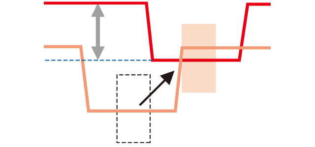
Profile correction function
The LS Series is equipped with a profi le correction function that corrects workpiece position deviation in terms of height, position and tilting when compared to the registered master and is effective for production lines that create deviation of the workpieces.
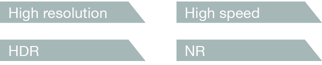
Four camera modes
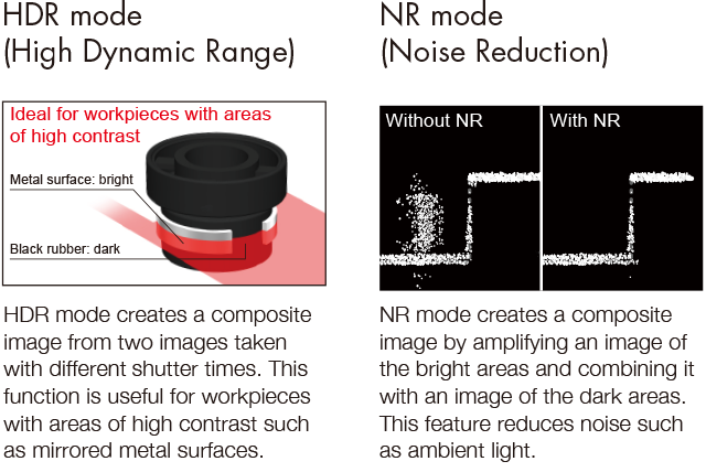
The LS Series incorporates four camera modes for stable imaging: a standard, high resolution mode; high speed mode, which captures images at four times the standard speed; high dynamic range (HDR) mode, which increases the range of brightness; and noise reduction (NR) mode.
Contact Us
Our experts quickly deliver the best plan for your needs and provide continuous support throughout the process.
- Download List
- 20